How occupancy and Vacancy Sensors Work. Where should occupancy sensors be used, and which type is better, hard wired or wireless? What’s the difference between an Occupancy Sensor and a Vacancy Sensor? What does ASHRAE 90.1 require for the controllability of lights in various spaces? Lighting consumes up to 20% of the total energy in commercial buildings. By adding lighting controls considerable energy can be saved based on space usage type and the type of light source, such as incandescent, fluorescent, high intensity discharge or LED.
If you prefer to watch the YouTube video of this presentation, scroll to the bottom or click on this link. How Occupancy and Vacancy Sensors Work
Why use an Occupancy Sensor?
Occupancy sensors are used to detect motion and provide a response by turning on or off lights or HVAC equipment. By monitoring when spaces are being used, a more energy friendly support system of lights and HVAC equipment can be deployed. Various sensing technologies are used, such as Passive Infrared (PIR) and Ultrasonic. There are other technologies such as Time of Flight (ToF), microwave, and camera based technologies that are not covered here.
Energy Savings Potential
According to a Commercial Building Energy Consumption Survey, the following savings can be achieved using occupancy sensors for the various space usage types.
Energy is saved by reducing lighting levels or shutting them off when a space is not in use. By adding lighting controls, you can save up to 90% or more of the energy used depending on the space usage type.
Types of Occupancy Sensors
Communication from the sensor can be hard wired or wireless. Although most sensors are probably hard wired there are some advantages to using wireless sensors in certain applications. Wireless sensors can be battery operated or use photovoltaic (PV) powered sensors and can be easily attached to a wall or ceiling. They’re a possible option where it’s difficult or aesthetically unappealing to run electrical wiring.
The material cost for wireless occupancy sensors is usually more than hard wired, but there will be labor savings from not having to install electrical wiring. Also, the ability to easily move a wireless sensor makes more sense for spaces with frequent layout changes.
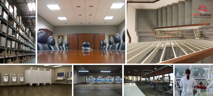
Where Should I Use an Occupancy Sensor?
The best candidates for occupancy sensors are spaces that are used intermittently, like bathrooms, meeting rooms, storage areas, classrooms, warehouses, private offices, and breakrooms. Areas to avoid putting sensors in are those that are busy or have a consistent occupancy level during a fixed schedule.
Two Lighting Control Strategies
The lighting can either automatically turn on when someone enters the room or require the occupant to manually flip a switch. These are referred to as an Occupancy or Vacancy sensor. The difference is that the vacancy sensor needs to be manually turned on, while the occupancy sensor turns on with motion. When the occupant leaves the room, both strategies will have the lights automatically shut off after a certain amount of time.
How do Occupancy Sensors Work?
The problem for the occupancy sensor is to accurately detect when occupants are present and when they have left the space. This includes the ability to recognize occupants working at their desk or on the other side of a partition. There are various occupancy sensors that accomplish these problems better than others. Here are some of the sensor technologies being used and their advantages and disadvantages. The two most used occupancy sensors are either ultrasonic sensors or passive infrared sensors.
Ultrasonic Sensors
An ultrasonic sensor will emit high-frequency sound waves that bounce around the room and objects, but are not heard by humans. The sensor will pick up any movement by noticing a change in sound wave frequency. This is based on the Doppler effect or Doppler Shift, which is the change in frequency of a wave in relation to an observer who is moving relative to the wave source.
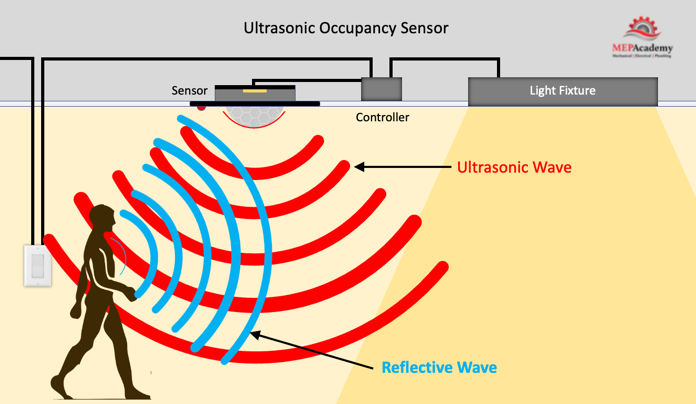
Since the Ultrasonic occupancy sensor sends out a continuous signal, the electrical power consumed will be higher than the wireless passive infrared sensor. This will require the ultrasonic to most likely be hard wired to provide the constant energy for operation.
Ultrasonic sensors are good at detecting movement that may occur behind a partition or bookcase which isn’t in the direct line of sight of the sensor. This technology will pickup slight movements of an occupant sitting at their desk reading a book or typing on their computer.
The ultrasonic occupancy sensor has a greater detection range than the Passive Infrared Sensors.
Passive Infrared Sensors (PIR)
An infrared technology-based occupancy sensor is best used in smaller open spaces without obstructions that allows it to easily detect movement. These sensors require that the movement occur within their direct line of sight, as they won’t detect movement behind a partition or bookcase.
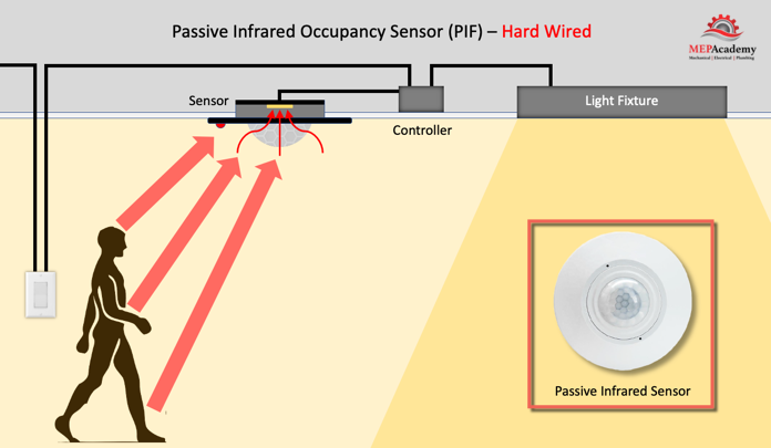
It’s called passive infrared because it doesn’t send a signal out. The sensor contains a thin film that generates electricity when exposed to heat which occurs when infrared energy is emitted from a warm object passes in front of the floor or wall in line of sight of the sensor. Because the infrared sensor doesn’t constantly send out a signal like the ultrasonic sensor, it doesn’t require the same amount of electrical power. This makes the passive infrared sensor a great option for wireless communication using a battery or PV cells for power.
The wireless passive infrared sensor will need a source of power for the controller that receives the signal from the sensor and interprets an output signal to increase or decrease lighting levels.
Wallbox sensors are made to fit in a standard electrical switch wallbox and use the voltage available at the box. This makes for an inexpensive and easy retrofit of an existing wall switch. They are limited by their range of vision.
How Long Should Lights Remain on After No Motion is Detected?
The time between no motion being detected and the shutting off or minimizing of the lights is dictated by various standards and codes. The National Electrical Manufactures Association (NEMA) has recommended that 15 minutes after no motion has been detected the interior lights should be shut off, and the 2021 IECC and ASHRAE 90.1-2019 have it at 20 minutes. Exterior lighting and parking garages have different requirements The shorter the time delay the greater the energy savings, but you also want to be sure not to have the lights going on and off too frequently.
Restrike Time
Occupancy sensors work best with light sources that have quick restrike times, that’s the amount of time it takes the light source to reach full value. Anyone who has witnessed the outage of a High Intensity Discharge light knows that it takes up to 15 minutes to reach full value. An outage occurred during a recent night-time football game, which had to be postponed long enough for the HID lights to come up to full brightness. This means that occupancy sensors are not a good choice for HID type lights but work well with quick starting light sources like LED, Incandescent and Fluorescent.
Where Should Sensors be Installed?
Sensors are best installed on ceilings or walls where interference from doors or air conditioning air flows are not a problem. Wireless sensors can be installed anywhere if motion is within the line of sight of the sensor. This allows wireless sensors to be installed where hard-wired sensors would be difficult to install.
Range of Sensors (Field of View and Coverage)
Wireless sensors need to be within 15 feet of the floor area or door to work effectively. Check the occupancy sensors manufactures literatures for specifics. If there are multiple obstructions in the space like partitions or bookcases, it may make sense to install hard-wired Ultrasonic type sensors which are better at motion detection in these situations. If wireless sensors are preferred, then more sensors will need to be installed to ensure motion is detected behind any obstructions.
Coverage or field of view can be in a narrow band like 8-degrees for use in corridors or aisles, up to a 360-degree circle, or a 180-degree semi-circle with diminishing capabilities at the extreme angles, and greater distance sensing abilities straight ahead. Sensors are also indicated by their coverage in square feet.
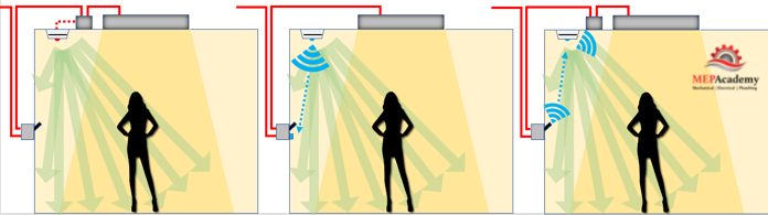
Multiple Levels of Lighting
In areas where there is natural sunlight, there is the option of using bi-level switching. The sensor will detect various levels of natural light and reduce the light fixtures output by half or some other percentage. Existing LED and fluorescent lights may need their ballast or drivers replaced to be compatible with the bi-level capabilities.
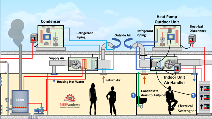
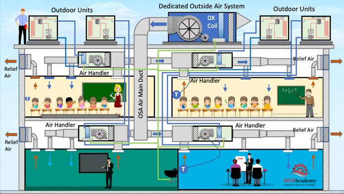
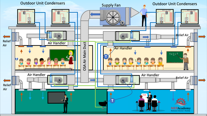
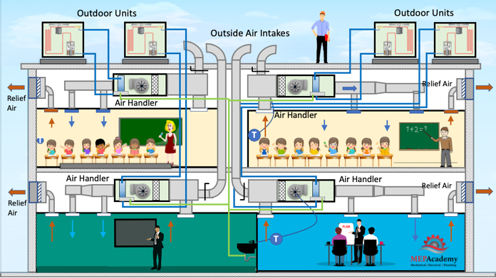
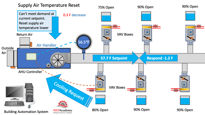
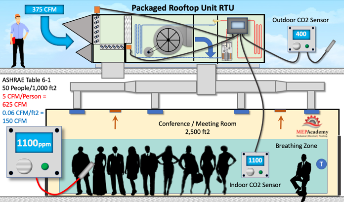
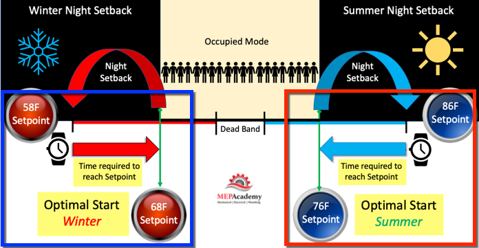
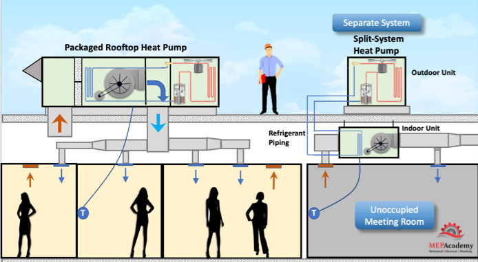
HVAC Controls and Occupancy Sensors
Occupancy sensors can save energy when integrated into the HVAC system control sequences. If the room is unoccupied, a signal can be sent to the HVAC equipment to reset the temperature, reduce the airflow or shut the system off. This would reduce energy consumed to condition an empty space.