Tuesday, June 17, 2025
Home Blog Page 41

Packaged Rooftop HVAC Units | RTU’s Explained

0
Packaged Rooftop HVAC Units RTUs Explained

We’ll cover Packaged Rooftop HVAC Units from 2-Tons to 162-Ton, and discuss their components and when to add a return or exhaust fan into the unit.

If you prefer to watch this presentation see our Animated Version on YouTube by scrolling to the bottom this article.

You’ll find Packaged Rooftop HVAC Units everywhere in small to medium sized Commercial buildings, including office buildings, restaurants, schools, entertainment centers, retail, grocery stores, condominiums, and shopping centers.

These units are often referred to as RTU’s (Rooftop Units), which cover everything from very small tonnage to over 100 tons, the Intellipak™ 2 from Trane goes up to 162-Tons. These larger ones are often called “Box Car’s” in the USA because they’re as large as a railroad box car.

Packaged Rooftop HVAC Units Explained

They provide the same benefits of heating and cooling as does your home air conditioner, they are just a little more sophisticated and contain additional features and functions which we’ll cover. Some of these features are required by code because they serve a commercial building.

There are many types of Rooftop Units (RTU’s) including 100% Outside Air Units (DOAS), Gas/Electric, Heat Pump, Straight Cooling, VAV or constant volume. Besides how they provide heating or cooling, all other components are similar.

Physical Size

Most of us are familiar with small tonnage units from 2 to 15 tons, but how big is a 150-Ton unit. Here is a quick size comparison between a 40-Ton to 75-Ton Rooftop Unit and a 2020 Tesla Model S.

Physical Dimensions of a Rooftop RTU versus a Tesla Model S Car

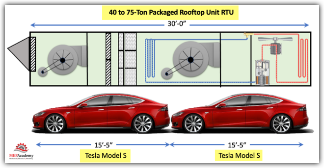
As you can see these Packaged Rooftop Units can be very long in length. RTU manufacture will use similar cabinet sizes for various ranges of Air Conditioning Tons, as the above cabinet will hold anywhere from a 40 to a 75 Ton unit. The differences is in the size of the various internal components, such as coils, fans, compressors, dampers and filters, but the cabinet is large enough to accommodate this range of sizes.

The other thing to consider is the weight of these units. So for reference here again is a quick look at a comparison based on weight. Can you guess what is heavier, a Tesla or a or a 25-Ton Rooftop Unit?

Weight of a Packaged RTU versus a Tesla Model S Car

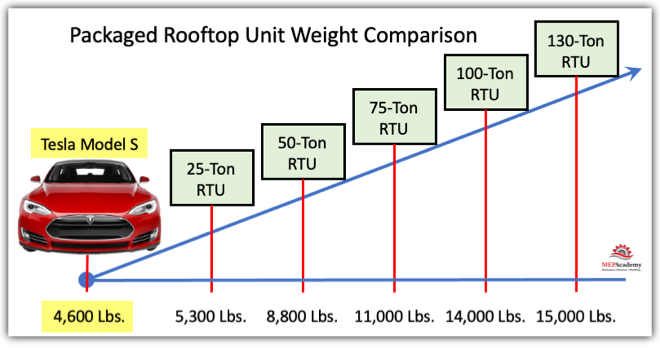
As you can see these RTU’s can get very heavy when put on a roof. It’s like parking many cars on your roof. This is why a structural engineer needs to make sure that the structure is designed to hold the weight.

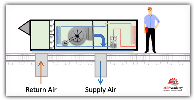
Supply Fan Only Configuration

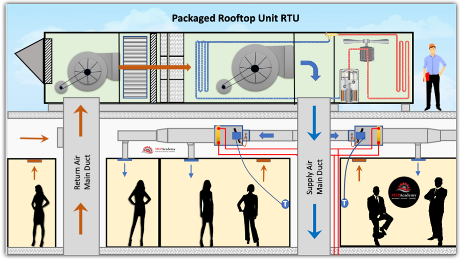
A Rooftop Unit with just a Supply fan is the most common configuration for small tonnage units. This can be used for small spaces, maybe a single classroom. To relieve building pressures a barometric damper can be installed in the space or within the RTU. This damper will allow excessive pressure to be relieved outdoors. The buildup of building pressure occurs during the economy cycle, when all that outside air is being pulled in from outdoors and sent to the space with no return coming back. The air has to go somewhere, so it looks for the path of least resistance such as crakes under the doors or open windows.

HVAC Packaged Unit with Supply Fan Only

Using only a supply fan with an economizer in a large building will make building pressure control difficult to maintain. Everyone has been in some building where the doors blow open, whistle or are hard to open because of the pressure relationship created by the HVAC system fans. That’s why on large systems is important to think about building pressure and adding a return or exhaust fan to the Rooftop unit.

Supply and Return Fan Configuration

Better control of building pressure is accomplished by adding a return fan. In this configuration the return fan can handle the static pressure of the ducted return, and the supply fan can handle the supply duct static pressure. There will be three sets of dampers that control the follow and volume (CFM) of the three air streams, Outside Air, Return Air and Exhaust Air. 

HVAC Packaged Rooftop Unit with Return Air Fan
HVAC Packaged Rooftop Unit RTU with Supply and Return Fans

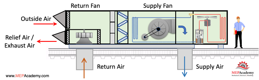
When in 100% economizer mode, the Return Damper will be 100% Closed because all the building air is being replaced with outside air, so the Outside Air Damper is 100% Open, this leaves the exhaust damper 100% open sending all the return air out of the building. This is where the use of an Energy Wheel can be applied, which we’ll discuss later.

Supply and Exhaust Fan Configuration

On larger units there is the ability to add an Exhaust Fan. In this configuration the Exhaust Fan will be used for building pressurization control. There will be a building pressure control sensor that will provided feedback on when to run the fan. The Supply Fan in this case will be responsible for the static pressure of the supply and the return system.

HVAC Packaged Rooftop Unit RTU with Supply and Exhaust Fans

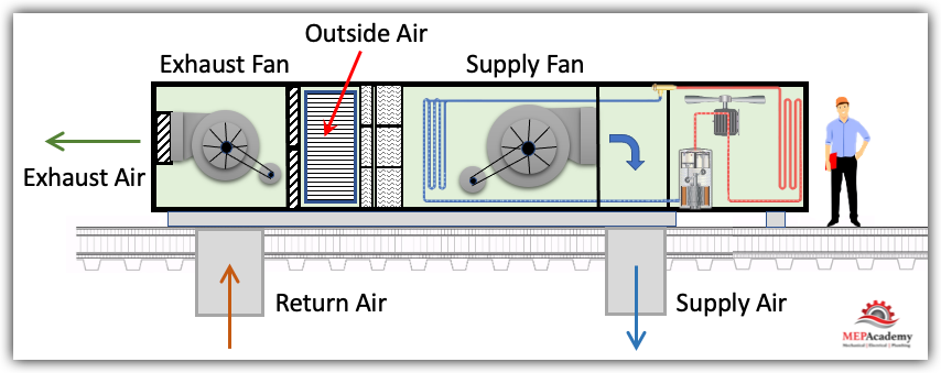
Since the Supply fan is responsible for the return air static pressure, this configuration works best with low static pressure return systems, like un-ducted return (attic return).

The exhaust fan will operate to maintain building static pressure by modulating its damper opening or fan speed, while the economizer (OSA Damper) is modulated to support ventilation requirements. 

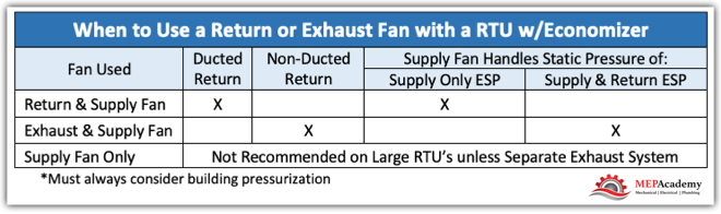
Here is an example of when to use a Return Fan versus and Exhaust Fan with an economizer.

Return Air Fans (Ducted Return Air Systems, external static pressure ESP exceeds 0.40”sp.)

Exhaust Air Fans (Non-ducted Return Air Systems, low external static pressure ESP return)

When Should you use a Return or Exhaust Fan on a Large Rooftop Unit?

Economizers

In many jurisdictions the use of an economizer is mandated to save energy when the outside air conditions are cool enough for conditioning the space. Economizers use the outside air to cool a building when the air outside is cold enough to assist or do all of the cooling. This allows for a reduction, or a total shut down of the refrigeration equipment (compressor), allowing for energy savings. In California, under Title-24 of the Energy Code, the requirement for an economizer is for any unit larger than 54,000 BTU’s, basically above a 4-1/2-Ton unit.

The amount of fresh air (Outside Air) is code driven and usually referenced in ASHARE Standard 62.1. The ASHRAE standard provides recommendations on how much outside air should be provided based on space usage type. For instance, an office space would require less outside air when compared to a conference room. 

Packaged Rooftop HVAC Unit Components

An economizer is basically a set of dampers and some control logic that opens and closes the outside air damper to allow more or less outside air into the building based on demand or code minimums. 

An important consideration when using an economizer in a commercial building is building pressure, which relates to the fan arrangement in the Rooftop Unit. On small tonnage units you can get away with just a Supply fan and a barometric relief damper. On larger units you may need to add a return or exhaust fan, especially if there is extensive return air ductwork.

Supply, Return and Exhaust Fans and Volume Control

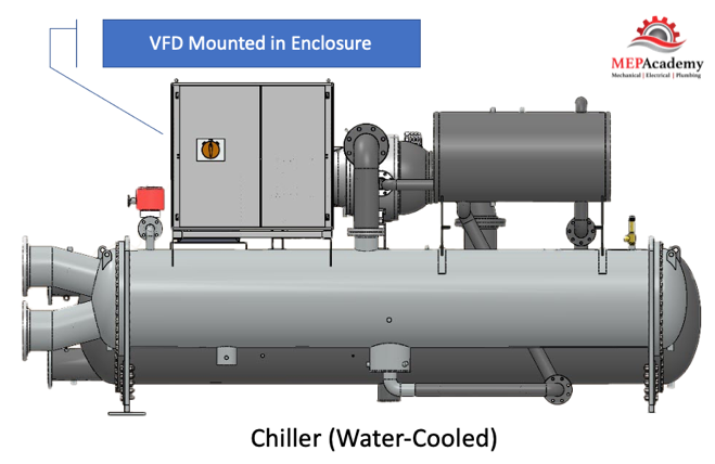
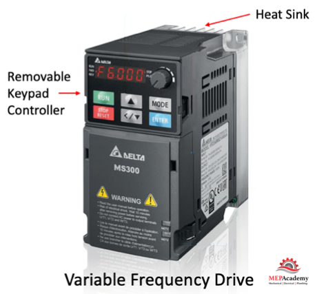
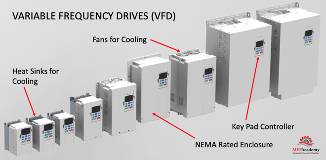
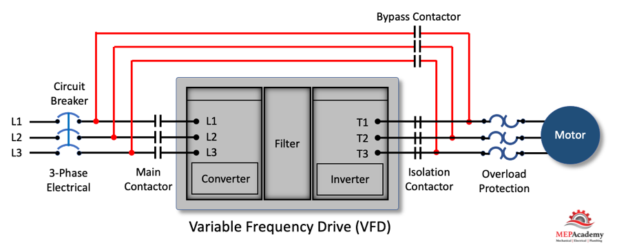
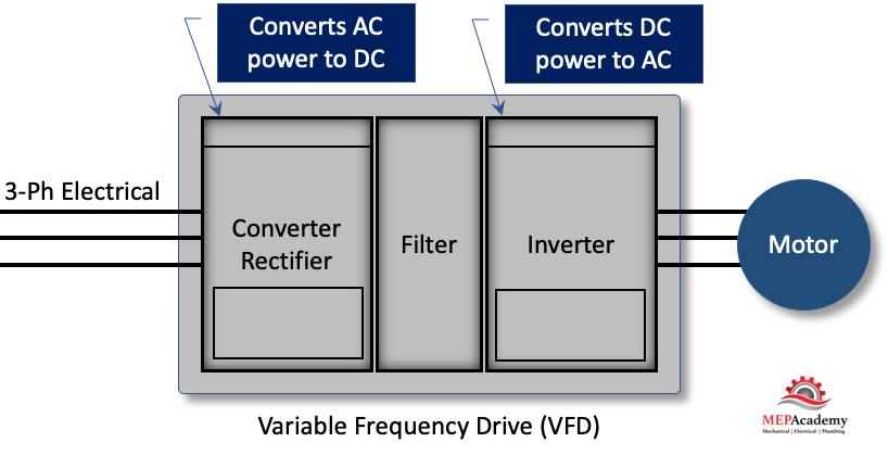
Depending on the size of the rooftop unit there may be a code requirement to have a variable speed fan. Using a VFD or ECM motor to reduce the volume (CFM) of air when the demand for cooling is reduced will save energy. This is often mandated by energy codes. (See our video on VFD’s to get a better understanding of how they work). 

The fans can be a belt-driven Centrifugal Type or a direct drive plenum style fan. Centrifugal style fans should be sitting on spring isolators to dampen any vibration from the motor. The supply fan is the other major energy consuming device in the Rooftop Unit besides the compressor.

Outside Air (Intake), Return Air and Exhaust Air Dampers

There will be an outside air opening for the intake of ventilation air as required by code to provide occupants with fresh air. This is often defined by ASHRAE Standard 62.1 for the ventilation requirements. The outside air opening may have an economizer depending on its size. Some codes require any rooftop unit over 36,000 BTU’s to have an economizer (check your local code). If the unit is provided with an economizer there will either be a relief air opening (barometric relief) for air leaving the building (not returned to the space) or a powered exhaust module to exhaust return air when the economizer is in operation. 

The quantity of air is controlled by dampers with actuators (small motors) to turn them from closed to open based on demand. These dampers will modulate their volume (CFM) based on the space requirements. The outside damper should never fully close because the code requires a minimum of outside air for the occupants.

Barometric Relief Dampers are usually used on smaller systems or buildings. As the pressure builds up in the building, this increase in pressure will force open the barometric relief damper located in the return section of the RTU or in the space, such as a classroom. There are no sensors, controls or motors to open the barometric relief damper, it’s opened strictly based on building pressure. These are usually used on small systems when the return air is non-ducted, such as in open ceiling plenum return.

On larger units look for the added feature of Outside Air measurement for better control. There will be aa means for measuring the volume (CFM) of air entering the RTU.

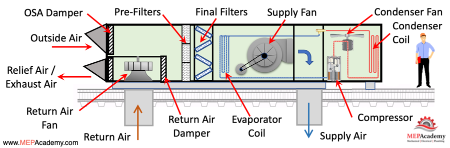
Refrigeration Circuit

One of the benefits of a Packaged HVAC Rooftop unit is that all the refrigeration components are in one cabinet, as compared to split systems where you’ll have an indoor and outdoor section connected by refrigerant piping. As the Rooftop HVAC units get larger, around 30-Tons or more you’ll find that there are two refrigerant circuits instead of one. This allows for better capacity control. If you’re not familiar with how a Refrigerant Circuit works, see our video explaining the Refrigerant Cycle. We will go over the location of the various components of the a complete Packaged Rooftop HVAC unit.

How Many Compressors, Refrigerant Circuits and Fans are in the various sizes of RTU's
How Many Compressors, Refrigerant Circuits and Fans are in the various sizes of RTU’s

Filtration

The amount of filtration goes from the minimum required to more extensive filters for the removal of contaminants that maybe harmful to the process the rooftop units is serving. Filters are rated by their MERV number, which is usually a minimum of MERV-13. There are special filters like HEPA filtration that increases the removal of dust and smaller particles in the air than a standard filter, but these are more expensive. There are also carbon filters for gas removal, and UV filtration to kill bacteria. Standard units will come with standard filtration, but these other options may be available upon request.

It’s important to keep the internal components clean, especially the coils where the heat transfer occurs. Dirty coils will reduce the effectiveness of the unit to coil or heat the building. Therefore, filtration is always before the coil.

There maybe several sections of filtration, including cheaper 2-inch thick MERV-8 pre-filters to the more expensive 12-inch thick MERV-14 filters.

Cooling Section

This section of the unit is where the heat transfer occurs between the refrigerant or heating fuel source. With a Heat Pump or Straight Cooling unit the refrigerant circuit feeds the coil with refrigerant from the compressor. 

Coils can be made with copper tubing and aluminum fins, or be all-aluminum microchannel coils. Other options are available like copper fins or coated coils. Coils are where the heat transfer occurs, so they should be kept clean by regular maintenance. 

Heating Section

Heating can be provided by Heat Pump (Electric), Gas, Hot Water or Steam. Most smaller RTU’s are going to be either a Heat Pump or Gas. The larger RTU’s provide options for various other method for heating, such as Hot Water or Steam. If using Gas for heating than there will be a stainless steel heat exchanger for transferring heat from the gas that is burning to the air going over the heat exchanger, the two never mix. The gas burners will be able to modulate the volume at some ratio like 4:1 in order to match the current demand of the space.

Preheat and Reheat Section

For colder climates there may be a need to provide reheat when the air leaves the cooling coil to ensure the supply air is within the target temperature setpoint.
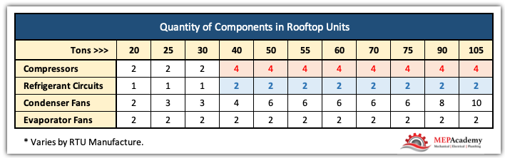
Compressors

This is the heart of the refrigeration cycle and where a lot of the energy is consumed providing heating or cooling for a space. Compressors can be inverter duty rated, allowing for variable speed and capacity control along with energy savings. There may be more than one compressor depending on the size of the unit, and there could be more than one circuit. The largest units, those around 40-tons and larger will have 4 compressors or more depending on manufacture. The compressors could be a mix of fixed and variable speed.

Condensers

Depending on the size of the unit and the location of the installation there are two choices for the type of condenser: Air -Cooled and Evaporative. The Evaporative Condenser is usually available starting at over 20-Tons. The condenser is the section of the refrigerant circuit that rejects heat to the surrounding atmosphere. The condenser coils are available with corrosion protective coatings for corrosive environments like seawater air.

Smoke Detectors

Often duct-mounted smoke detectors are required over a certain size unit, like everything over 2,000 CFM requires a smoke detector to shut-down the rooftop unit when smoke is detected. This helps prevent the spread of smoke through-out the building. It may be possible to have the smoke detector mounted within the rooftop unit. This will save time and money by not having to mount and wire the smoke detector to the unit. There may be an additional requirement for remote monitoring at a fire control panel, which would be the scope of the Fire/Life Safety contractor.

Curb or Platform Mounted

The Rooftop Unit can either sit on a manufactured curb, which is often the case with down-shot units or they can sit on a platform, often with side discharge units. A down-shot unit is one where the supply and return ductwork come out of the bottom of the rooftop unit, and a side discharge is just as the name implies where the supply and return ductwork comes from the side of the unit.

A curb mounted unit will require holes in the roof to be cut beneath the curb to allow for the supply and return ducts to enter the building. A platform mounted Rooftop unit will have supply and return duct openings cut in the roof somewhere further away from the unit to enter the building.

On the larger RTU’s the curb will not extend under the Condenser section. In these cases, the condenser will be provided with support rails. This is meant to mitigate any noise coming from the compressors and condenser fans being transmitted through the supply duct into the building.

Factory Startup and Training

On the larger RTU’s you might want to take advantage of the manufactures option for factory startup assistance and training. This will depend on how comfortable your technicians are with the type of RTU being installed. Make sure to add this cost to your estimate if you plan on using this option.

Controls

Controls can be fully integrated, and factory installed ready to go with an interface panel mounted on the Rooftop Unit. The larger units may have static over-pressurization protection on RTU’s with VFD’s. There will be communication interface modules for LonTalk, BACnet or manufactures proprietary interface to allow for connection to a building management system or remote monitoring. This allows for control of the unit from anywhere with an internet connection. Some RTU manufactures offer WiFi control of their units, which eliminates the need to hardwire the controls.

On larger RTU’s there is the ability to control the Supply, Return and Exhaust Fans with VFD’s. 

The use of Fault Detection and Diagnostics (FDD) with RTU’s that have an economizer is to ensure that notice is given if the economizer or outside air damper is not working correctly. Economizers or outside dampers are notorious for not working, which has led to additional code requirements and testing.  The FDD is meant to give notice if a fault occurs, because improperly functioning economizers are a waste of energy and or lack the necessary volume of ventilation air required for a space.

Humidifiers

There are various optional components that can be added to a custom RTU, such as a humidifier. The humidifier adds moisture to the air to maintain a certain range of Relative Humidity because of some process or space requirement.

Electrical

Some of the larger RTU’s come with more than one entrance point for the connection of the electrical. Most codes now require some form of electrical convenience outlet within a certain distance of the RTU for service personnel. The larger units may have the option of having a convenience outlet already installed on the unit.

Energy Recovery Wheel

Another option is to have an Energy Recovery Wheel installed in some of the larger Rooftop Units to increase the energy savings when using large amounts of outside air (Ventilation Air). The Energy recovery Wheel will capture heat and moisture that is being exhausted and transfer it to the incoming outside air that is being used for ventilation air. This will save from losing this energy because of the need to provide ventilation according to ASHRAE 62.1. An Energy Recovery Wheel can be used on 100% Outside Air Units or Rooftop Units with Economizers. Energy Recovery is mandated in most of the USA when you reach a certain minimum percentage of ventilation air and exceed certain flow rates (CFM)

Sound Attenuators

Some manufacturers off the option of sound attenuators to reduce the noise levels emanating from the rooftop unit. These are usually installed downstream of the supply air fans to reduce the transmission of noise from the fans into the building. 

Rooftop Unit RTU Cabinet and Housing

Since these units are installed outdoors, they need to provide protection from the elements, whether that’s the sun, rain, snow, wind, or salty ocean air. The units come standard with zinc coated galvanized steel and painted to match the manufactures standard color. We’ve all seen cars that reside near the beach and how corrosive the salt air is to the paint. 

There are special coatings for the housing and the internal components like coils if required because of coastal locations. They also need to provide for thermal integrity using interior thermal lining or optional double wall construction with foam injected insulation.

The Rooftop unit needs to be completely weatherproof but allow access when being serviced. This requires that various access doors are installed in key location around the unit. Often these doors are located to allow for filter changing and coil cleaning, in addition to access to controls, electrical and the compressor section. 

The evaporator section will have a drain pan often made of stainless steel. The supply and return air duct connections come off the bottom with the option on some models to have a side discharge configuration.

The larger RTU’s come with lifting lugs for rigging using a crane.

SUMMARY

The use of a Rooftop HVAC Unit allows for easy installation within a wide range of sizes, from 2 to 160-Tons. With various options available for humidification, energy recovery, economizers, UV lights, sound attenuation, VFD’s, roof curbs coil and cabinet coatings for protection, and increased filtration. There are various fan arrangements for building pressure control when RTU’s serve larger buildings or multiple spaces. Adding a Return Fan provides better building pressure control with a ducted return.

Packaged HVAC Rooftop Units RTU

How to Figure Construction Labor Rates with Burden

0
Construction Labor Rates with Labor Burden

There are two types of Construction Labor Burdens, one is mandatory and the other we’ll call additional Indirect Labor Burden. We’ll explain the difference and show you how to figure construction labor rates with burden. Applying the mandatory burden rate is basic math dependent on the current rates dictated by government agencies. There are no options with these cost and they’re directly related to the employees earned wages.

If you Prefer to Watch a Video of this presentation, scroll to the bottom for the Video or Click this link —-> Construction Labor Rates with Burden

Additional Indirect Labor burden rates are not dictated by law but are required for you to recover the cost of certain aspects of running a construction company, often referred to as indirect cost, a part of operating expenses.

Construction Labor Rates with Burden

Labor wages are built from the three categories of Labor, 1) Employees Base Wage & Benefits, 2) Mandatory Labor Burden, and 3) Additional Indirect Labor Burden

#1 Wages and Benefits (Base Wage)

  • Base Wages
  • Vacation
  • Health & Welfare
  • Union Benefits

#2 Mandatory Labor Burden (Mandated by Law to Pay)

  • Workers Compensation Fund (Can be self-insured)
  • FICA
  • FUTA (Federal Unemployment Tax)
  • State Unemployment Tax
  • Liability Insurance (Can be included Elsewhere)

#3 Additional Labor Burden (Cost to be Recovered)

  • Vehicles (Lease payments, Maintenance, Gas, Repair, etc.)
  • Small Tools
  • Uniforms
  • Cell Phones, iPads, etc.
  • Training
  • Warranty Cost
  • Travel
  • Supplies
  • Non-working Hours

There are several ways to handle these additional cost when running a construction company. A company can either add these cost to the labor rate as we’ll show you in a minute, or you can add them as a percentage of a line item on your estimating spreadsheet. Here are the steps to take.

Step #1 – Determine the Annual Cost for Each Category

Depending on how you plan to calculate the various categories of cost, or based on the capabilities of your accounting system, cost should be broken out in as fine a detail as makes sense for your company. Here is an example for three Foreman that are provided with company vehicles.

Example:

  • Vehicle Leases $12,000 x 3 = $36,000/Year
  • Vehicle Insurance = $3,600
  • Vehicle Maintenance = $2,500
  • Vehicle Fuel = $15,000
  • Total Annual Vehicle Cost = $57,100
Vehicle Cost Recovery - Labor Burden
Vehicle Cost Recovery – Labor Burden

Step #2 – Determine Billable Hours (Hours Paid vs Billable Hours)

Company employees will be paid for days that they’re not at work (Vacation, Holidays, Sick Time), and for days working but not billable (Training, Meetings, Misc.). The net will be the employee’s billable hours. Using the previous year’s billable hours as a starting point, add your projected billable hours for the current year for all the employees you are calculating a burden rate for. Here is a quick look at the 3 Foreman we used in the above vehicle example, and the two ways to look at this; the right way (billable Hours) and the wrong way (paid hours).

  • Employee Paid Hours = 2,080 x 3 Foreman = 6,240 Hours
  • Employee Billable Hours = 1,600 x 3 Foreman = 4,800 Hours

If Burden Recovery Based on:

  • Paid Hours ($57,100 / 6,240 Hrs. = $9.15/Hr.)
  • Billable Hours ($57,100 / 4,800 Hrs. = $11.90/Hr.)

You can see that if you used the paid hours to try and recover the cost of furnishing a vehicle for these employees, you would end up short of the cost. Actual Billable Hours x $9.15/Hr. = $43,920, a difference of <$13,180>. 

The correct method is to use billable hours, which is 23% less than paid hours, or stated differently you have an employee utilization rate of 77%.

Billable Hours / Paid Hours = 77%

Step #3 – Calculate Labor Burden Rate

Take the total cost for any category and divide it by the total billable hours applicable to that category. In the example above we were only looking at Foreman Vehicles, and how much cost we needed to added to their hourly rate to recover the cost of furnishing the Foreman with those vehicles. ($57,100 / 4,800 Hrs. = $11.90/Hr.)

This can be done for any department where you can track the cost, and then divide those cost into the billable hours for those employees to derive at a labor burden rate. 

Three Methods of Cost Recovery

The following three methods of cost recovery are the ones we have seen most commonly used from small to large contractors. Smaller companies tend to lack the accounting software and personnel to track cost by categories. They might use of a flat percentage rate, like adding 30% to direct labor, or add these cost to their overhead percentage, which is mixing overhead expenses with operating expenses.

Three Common Methods of Cost Recovery in Construction

For an example let’s say a small company has the following cost that they want to recover, this is in addition to the Mandatory Labor Burden which is easily calculated.

Operating Expenses

  • Vehicles $57,100
  • Small Tools $10,000
  • Uniforms $3,200
  • Cell Phones $8,500
  • Training $2,800
  • Total $81,600

Project Revenue & Cost for Previous Year End

  • Total Revenue $1,200,000
  • Project Cost $1,000,000

Total Billable Hours

  • (3) Technicians with Trucks 4,800 Hrs
  • (2) Helpers (No Vehicle) 3,200 Hrs
  • Total Billable Hours of 8,000 Hrs

Overhead Method

The expenses we are talking about are related to “Operating Expenses” as opposed to true “Overhead Expenses”. But, for smaller companies that lack the accounting system required to track cost according to some categorization, the use of the overhead percentage makes for a quick calculation. They take all their indirect expenses, and divide it into total project cost, to come up with an additional percentage to add on top of their normal overhead percentage.

$81,600 Operating Expenses / $1,000,000 Project Cost = 8.16%

Labor Burden Method

With this method there are several approaches as we already demonstrated one of them using the vehicle cost above divided by the billable hours of the Foreman. ($57,100 / 4,800 Hrs. = $11.90/Hr.). The second method is to take the total ‘Operating Expense and divide it by the total billable hours including the helpers. We prefer the first method as being more accurate, because it’s the Foreman who are benefiting from the vehicles and it is their hours that dictate the usage of the vehicle, but here is what it might look like as an overall labor burden to every category of labor.

$81,600 Operating Expenses / 8,000 Billable Hours = $10.20 / Hour

% Category Method

With the “% Category Cost” method, total the cost related to a particular category, such as small tools or warranty cost, and then divide that into one of the cost items in your estimate, whether total cost or total labor cost to get a percentage to use when bidding new work. For example adding 1% of total labor on each bid to cover the cost of small tools. Here we use total project cost.

Small Tools $10,000 / $1,000,000 Project Cost = 1%

Or if you had a project manager that was costing you $50,000/year you could add 5% to every bid to cover this cost based on the company performing $1,000,000 in cost a year.

Project Manager $50,000 / $1,000,000 = 5%

With any of the three methods above there is a chance of not recovering your full cost. This occurs in each of the three methods because of the following;

Cost Recovery Methods

#1 Overhead % – The company can fall short of full cost recovery because they didn’t meet their sales goals, and didn’t perform the total amount of work in gross dollar amount to recovery the predicted cost.

#2 Labor Rate Burden – The company can again fall short of total cost recovery because they didn’t charge enough billable hours during the year to recover the cost. Remember the labor burden is based on a number of billable hours occurring in the year, if that doesn’t happen, then you fall short of recovering your cost for those items.

#3 Category Cost – the same thing happens to category cost when the category used for the calculation doesn’t hit the amount used to forecast the threshold for full cost recovery. If you figured small tools at 1% of your labor cost and you didn’t have as much labor this year as expected, than you won’t recovery your small tools cost.

Labor Burden Recovery Fund

The construction labor burden isn’t part of the employees take home pay, but part of a pool of money to be recovered for the cost of various items of the trade needed to carry out the business. You can have a labor recovery fund for various departments or categories of cost, for instance; Foreman Trucks, Shop Fabrication, Detailing Department, Project Management, Small tools and equipment. These are just a few of many possibilities. 

Cost Recovery Categories for Construction Companies

The important thing to know is what these cost are annually, so that you can account for them in your hourly rate or as a percentage of cost on your estimating spreadsheet. The companies accounting system should be able to tell you what you have spent on various cost categories, we’ll call them Cost Recovery Buckets. If you have a Vehicle Cost Recovery Bucket, then you’ll need to fill that bucket by the end of the year with enough money to pay for all the cost associated with the vehicles you provided your employees for that year.

Other Methods of Cost Recovery

There are different ways being advocated for figuring construction labor rates with burden, with the most common being the addition of a percentages of your direct labor cost. For example, some contractors may just add 30% to their direct cost (Wages with Benefits) and call it a day. But is this accurate; are you sure you have recovered all your cost? For smaller companies this might work, but as you grow, the buckets of cost to recover start to grow and will need a deeper analysis.

Labor Burden Review and Tracking

It’s important to track and review your labor burden calculations on a regular basis. The time interval will depend on the size of your company and the ability of your accounting software to report the proper information. You may want to review the numbers every quarter, or semi-annually, but the more frequent the better to allow you to make adjustments as needed to meet the actual cost.

Were you under recovered, or did you work more hours than forecasted and have a surplus in your recovery account?

How to Establish a Labor Burden Rate for Your Company

You may need to calculate more than one labor burden rate based on the various classifications of workers or departments. For instance, you might have Electricians, Plumbers, HVAC Technicians, and then within each of these trades there maybe various levels of experience that warrant an increase in their labor rate for various benefits, such as providing all Foreman and Journeymen with trucks. This would then require you to recover the cost  of the vehicle and the associated cost of maintaining and operating the vehicle.

You might also want to calculate the burden rates based on departments, such as, Sheet Metal Fabrication Shop, Detailing Department or Warehouse and Shipping. The point is to understand the cost of providing the particular benefit and then recover the cost by adding a labor rate burden to that category of labor or use a percentage of cost line item on your estimating spreadsheet. Each company will look at this differently based on their modes of operation and the sophistication of their accounting system to track these cost.

There are various cost of running a construction company that may not be covered by your overhead and profit margin. Labor burden is cost in addition to your wages and fringe benefits. Knowing your labor burden will help you set the correct labor rate for all your work.

Summary

Having a good accounting system will make calculating construction labor rates with burden easier. Be sure your accounting software allows for categorization of cost according to your needs. Understanding all the indirect cost associated with your labor is important in running a successful business. The important thing is to understand these cost and develop the most accurate way of tracking and measuring them before the year is over and it’s too late to make an adjustment. One of the ways to add more money to your recovery fund is to perform more billable hours than anticipated.

Construction Labor Rates

What is a BTU or Ton of Air Conditioning

0
What is a BTU or Ton of Air Conditioning

The capacity of everything from refrigerators to air conditioners is rated in BTU’s or Tons. So what is a BTU, and how do they relate to Tons of Air Conditioning?

You’ll find a Video of this article if you prefer to watch, just scroll to the bottom.

Definition of a BTU

First of all what does a BTU stand for, “British Thermal Unit”

The definition of a BTU is “ The amount of heat required to raise the temperature of one pound of water one degree Fahrenheit”. It doesn’t matter whether you are adding heat or taking away heat from water, it’s the same definition and calculation.

What is a BTU in Refrigeration or Air Conditioning

One Ton of Refrigeration or Air Conditioning

So, how did they come up with the term Tons. This comes from the fact that a TON (2,000 Lbs.) of ICE will absorb 288,000 Btu’s in 24 hours. And, since everything is rated by the hour, we divide by 24 hours to get the equivalent of 12,000 Btu/Hr.

288,000 Btu’s / 24 Hours = 12,000 Btu’s/Hr.

What is a Ton of Refrigeration or Air Conditioning

It’s still hard to wrap your head around just how much a BTU is in relationship to everyday common items around you. So. Here are some interesting facts about various outputs of BTU’s.

Heat (BTU’s) Generated by People

One of the factors contributing to the heat gain of a space is people. Depending on what people are doing they generate various amounts of Btu’s. The more active, the more heat (Btu’s) added to the space. (See diagram below)

Total Heat Generated by People in Various Levels of Activity

Heat (BTU’s) Generated by Lights

With the transition away from Incandescent lights there is a corresponding savings in the heat output. A 100 watt Incandescent lightbulb puts out about 341 Btu/hr, while an equivalent lumens LED of 15 Watts produces 51 BTU/Hr.

BTU's Generated by Lighting
BTU’s Generated by Lighting

Of course when doing a Heating and Cooling load there are more factors involved, but this gives you an idea of how various activities and items generate heat (Btu’s).

Refrigerators, Air Conditioners and Gas Stoves

When looking at Refrigerators, Air Conditioners or Gas Stoves, and you see the Total BTU’s, but realize that this is the amount of heat that can be absorbed or produced within an hour. It’s BTUH (BTU’s per Hour). 

How Air Conditioners are Advertised

You can see that Air Conditioners are advertised using three different indications of its size.

How Air Conditioners are Rated and Advertised


#1. The first one there shows that it produces 24,000 Btu’s, which is a 2-Ton unit as we learned earlier. Take the 24,000 Btu’s/(12,000 Btu’s/Ton) = 2-Tons

#2. The second example shows that it’s a 3-ton unit, so we know that this produces 36,000 Btu’s/Hr. Take the 3-Tons x 12,000 Btu’s/Ton = 36,000 Btu’s

#3. The third example indicates that it produces 24k BTU, which in this case “k” stands for thousands, so this is a 24,000 BTU/Hr. air conditioner, or a 2-Ton unit. (24,000 / 12,000 = 2)

Refrigerators

With refrigerators there is almost no mention of capacity in terms of BTU’s or Tons. Instead it’s all about the width, or cubic volume of the interior space. How much food can you get in the refrigerator. You don’t worry about the BTU’s as its assumed that whatever size refrigerator you buy will be able to handle the heat from whatever you decide to put in it.

Refrigerator Ratings

Gas Appliances

With gas stove tops or other gas appliances it’s important to check out the BTU rating of the total unit, and for each of the individual burners. As can be seen in the sales image below, the advertised information is related to the appliances size. Of course the size is important when selecting a stove top or gas appliance, but so is its BTU capacity. The larger the BTU burner capacity, the faster your food will cook. 

Gas Stove Top Ratings

Check the specifications of the appliance to see what each burner is rated for, could be anywhere from 500 to 18,000 Btu’s per burner, a big difference. You can see in the image above that the burners vary in their diameter, which is indicative of their Btu capacity.

BTU Calculation Example

For example, if you had a Gas Stove and one of its burners was rated for 5,000 BTU’s, you could calculate how long it might take to heat your water, realizing and ignoring that there are losses to the surrounding space. Not all heat gets absorbed, but just for simplicity this is how the calculation would work.

Starting with 2 Lbs. of water at 65F, and wanting to raise it to 210F, just before the boiling point of 212F.

BTU’s = Weight of Water (Lbs.) x Temperature Difference

BTU’s = 2 Lbs. x (210F – 65F)

BTU’s = 2 x 145

BTU’s = 290

290 BTU’s / (5,000 BTU/Hr.) = 0.058 Hrs. or 3.48 Minutes

So, what is a BTU or Ton of Air Conditioning? We now know that a Ton of Refrigeration or Air Conditioning is equivalent to 12,000 Btu per hour.

Watch the Video of “What is a BTU or Ton of Air Conditioning”

How Variable Frequency Drives Work in HVAC Systems

0
How Variable Frequency Drives Works

We’ll discuss the basics of How Variable Frequency Drives (VFD’s)Work in HVAC Systems, also referred to as Variable Speed Drives (VSD’s), which are used in the Mechanical Construction Industry for the control of motors that run fans, pumps, and compressors. We’ll discuss where VFD’s are used in the MEP Construction Industry, Identify the key components of a VFD and how to select a Variable Frequency Drive.

If you prefer to watch a Video of this presentation than scroll to the end this article for our YouTube Video.

Be sure to shutoff any electrical power when working with a VFD.

Motor control equipment and electronic controllers are connected to hazardous line voltages. Extreme care should be taken to protect against shock and possibility of a fatality.

Where are VFD’s used in the Mechanical Construction Industry?

Pump Control with VFD’s

The use of VFD’s to control the motor speed of pumps is widely used in commercial construction projects. There are various control strategies, and as the image shows this one uses a “Differential Pressure Transmitter” to control the speed of the pump, which controls the flow (GPM) based on demand. 

How to control pumps using Variable Frequency Drives VFD's
How to control pumps using Variable Frequency Drives VFD’s

As the HHW control valves open due to an increase in demand for heating hot water, the pressure drops in the piping which is sensed by the Differential Pressure Transmitter. The transmitter sends a signal to the Variable Frequency Drive to speed up (increase flow – GPM), causing the pump to push more water through the pipes. The opposite happens when the heating hot water valves start to close because the space is warm enough. The valves start closing causing an increase in pressure in the piping which is sensed by the differential pressure transmitter. The transmitter sends a signal to the Variable Frequency Drive to slow down the pump motor, reduces the flow (GPM).

Checkout these Variable Frequency Drives here

Fan Control with VFD’s

The theory is the same for controlling the speed of the fan motor. There is some form of monitoring of the supply air duct which will cause an adjustment to the speed of the fan. In the scenario below we show that a “Static Pressure Sensor” is located two-thirds of the way down the main supply air duct. The sensor will pick up changes in pressure within the duct.

Controlling a Fan Motor using a Variable Frequency Drive - VFD
Controlling a Fan Motor using a Variable Frequency Drive – VFD

As the Variable Air Volume (VAV) boxes begin to open their dampers because of an increase in cooling demand, the pressure in the supply duct drops. When the pressure in the supply air duct decreases, the Static Pressure Sensor sends a signal to the Variable Frequency Drive to increase the speed (RPM) of the fan motor, causing an increase in CFM. The opposite happens when the VAV box dampers begin to close because the spaces are cold enough. As the dampers begin to close the pressure in the supply air duct increases, causing the Static Pressure Sensor to send a signal to the VFD to slow down the motor of the fan, reducing the amount of CFM. See our video on Variable Air Volume Systems.

Compressor Control with VFD

Chillers come with various options for variable speed control. Check with your Chiller manufacture for chillers with Variable Speed Drives. As the load in the building decreases, the chiller can change the speed of the motor that turns the compressor, thereby reducing the energy consumed.

Compressor motor on a Chiller using a Variable Frequency Drive - VFD
Compressor motor on a Chiller using a Variable Frequency Drive – VFD

By reducing the speed of the compressor the output tonnage of the chiller is matched to the demand. Variable Speed Drives (VSD) come mounted in an enclosure mounted on the chiller.

Checkout these Variable Frequency Drives here

Old Methods of Volume Control

To control the volume of air (CFM) or water (GPM) using constant speed motors required putting an artificial load on the system. This method of flow control waste energy. Fans used dampers to impose flow restrictions, while pumps used valves (throttling) to dial back the GPM flow of water or just bypassed the water. These methods generate restrictions to flow that waste energy. Controlling the varying flow requirements with a VFD saves on this lost energy.

In the HVAC industry the use of Variable Air Volume System is very common. To control the various cooling and heating load fluctuations during the year the Air Handler fan will vary the volume (CFM) delivered to the space. The same applies to the Chilled Water, Heating Hot Water or Condenser Water flow (GPM) through the pipes as the load on the building changes through-out the year. In older HVAC piping systems with constant flow pumps the use of 3-way valves was common. Instead of reducing the flow (GPM), the water would bypass the coil through the 3-way valve. Obviously this is a waste of energy as the pump is just circulating water that is not needed.

What Is the Purpose of a Variable Frequency Drive VFD?

The main purpose of a Variable Frequency Drive (VFD) is to vary the speed of a motor by varying its frequency and voltage to provide for energy savings. By increasing the frequency you can increase the speed of the motor, and by decreasing the frequency you can decrease the speed of the motor, it’s basically that simple. 

Many of the existing motors that control mechanical equipment were originally designed to run at constant speed, which isn’t energy efficient. These older motors were either in the on or off position and used some form of artificial resistance to control flow.

Variable Frequency Drive - VFD
Variable Frequency Drive – VFD

How to Choose a Variable Frequency Drive VFD

Selecting a Variable Frequency Drive can be very simple when you know the Voltage, Current and the Power Rating.

When bidding a plans and specifications project the mechanical engineer will have sized and documented the required VFD on the equipment schedule. If you’re doing a Design/Build project or Retrofit where you’ll be responsible for the selection of the variable frequency drive, then knowing the basic’s for selecting a drive is crucial. If you’re not comfortable with selecting a Variable Frequency Drive there are many VFD suppliers that will help you choose the correct drive.

Checkout these Variable Frequency Drives here

Here are a few things to consider when selecting a Variable Frequency Drive (VFD) for an existing motor on your project. Values are from example motor nameplate below.

  • Full Load Amps (FLA) 40-37/18.3
  • Horsepower (Hp) 15
  • Voltage (V) 208-230/480
  • Speed (RPM) 1775
  • Motor Type – (Inverter-duty Rated)
  • Method of Control I/O (Static Pressure Sensor, Differential Pressure Transmitter)
  • NEMA Enclosure type. (Inside, Outside, Exposure to elements) 

The first place to start on an existing motor is the motor name plate. This is where most of what you need can be found. Hopefully the building engineer hasn’t removed them or painted over them.

Motor Nameplate
Motor Nameplate

Motor Nameplate

The motor name plate may indicate more than one voltage and its corresponding amperage. The above name plate indicates 230 and 460 volts, with a corresponding 37 and 18.3 amps. The higher the voltage the lower the amps.

Full Load Amps (FLA)

The full load amps (FLA) is one of the important aspects of the Variable Frequency Drive VFD selection process. For existing motors this number will be on the motors nameplate, and shown as 40-37/18.3 on example nameplate. Why three values? Each FLA corresponds to what voltage is used, either 203 Volts (40 FLA), 230 Volts (37 FLA) or 460 Volts (18.3 FLA)

Frame Number

The NEMA frame number can be two or three characters and represents the distance from the center of the motor shaft to the center bottom of the mounting plate. Such as in our example of a frame number of 254T. This equals 254/16 = 15.875” 

Method of Control

If the VFD is for controlling a fan in a VAV Air Handler, then the controller may be a “Static Pressure Controller”, see our Video on Variable Air Volume Systems that explains this further. If for a pump, may be your using a “Differential Pressure Controller”. Whatever system variable is being measured the Input and Output (I/O) signals need to be setup in the VFD.

NEMA Enclosure Type

The Variable Frequency Drives are usually located in Mechanical Rooms or Outside near the equipment. Depending on the type of environment that surrounds the VFD, there are various solutions for the enclosure type as indicated by the NEMA number. The most common in the Mechanical industry is NEMA 1, 3R and 12. 

Variable Frequency Drives - VFD's (Small to Large Horsepower Drives)
Variable Frequency Drives – VFD’s (Small to Large Horsepower Drives)

NEMA 1 Rated enclosures are made for Indoors with no water protection. NEMA 3R is rated for Indoor or Outdoor use, and where rain, snow or ice may form. NEMA 12 is rated for Indoors and with dust, lint and other dirt circulating in the air, along with minor water splashes. There is an enclosure for any environment.

Since VFD’s produce heat during operation, this must be part of the consideration when selecting a ventilated enclosure versus a cooled enclosure. Avoid locating a VFD on a heated wall or in direct sunlight. 

Checkout these Variable Frequency Drives here

Variable Frequency Drive – VFD Components

Bypass

The bypass provides a means for circuiting around the drive and providing power to the motor. You have to be sure that in bypass mode the motor still has some form of overload protection. Purchasing a Bypass adds substantial cost to a VFD. If its not needed or you can afford some down time with the equipment, then avoid purchasing a bypass or if you have several VFD’s of the same size, just purchase an extra drive for emergency replacements.

Variable Frequency Drive with Bypass

VFD Keypads and Control Panels and Remote Monitoring

If the location of the VFD is inaccessible or inconvenient for the maintenance staff, you could mount the VFD’s Keypad remotely. You may need additional cabling, so check with the VFD manufacture.

Navigating is easy using the control panel to set various parameter values. Various VFD manufacturers drives have the capability of copying settings from one drive to others. The control panels provide a touchscreen graphical display in various sizes from 3.5” up to 15”

Look for optional remote monitoring that allows you to view and control the drive from any location with web access.

The available menu items will vary by VFD manufacturer and how they are displayed, but there are some basic common features. There will be a way to adjust the speed, bypass the VFD if provided with a Bypass, alarm and fault indicators, on/off/auto, indication that either the I/O Terminal/Keypad or Communication Bus is chosen for control of start/stop – signals.

Input Line Reactors and Harmonics

To protect the VFD from the utility companies possible power fluctuations an input line reactor is installed. The Input line reactor also helps mitigate the harmonics associated with the use of variable frequency drives.

Physical Size

Small drives can be anywhere from 12” in height to over 60”. The weight of a small drive can be 10 pounds to over 500 pounds for larger drives.

VFD Cooling Requirements

There are two methods to keep Variable Frequency drives cool; air-cooled and liquid-cooled. Liquid-cooled is used on larger VFD’s, so most likely you’ll be dealing with air-cooled drives. Cooling is required to remove heat from the semi-conductors and ancillary devices used in the VFD.

The VFD’s require space around them for the proper flow of air through the cabinet to allow for cooling the drive. Be sure to check the mounting instructions to avoid overheating a drive and causing premature failure. Small VFD’s require anywhere from 40 CFM to over 1,000 CFM for larger drives. Check the drive manufacturers requirement for space around the drive and their method of cooling the unit. The area around the air-cooled VFD should be kept clean, dry and free of dust.

Three Main Components of a VFD

The following are the three main components that convert AC Voltage to DC Voltage and then back again using a simulated AC Voltage.

Three Main Components of a Variable Frequency Drive - VFD
Three Main Components of a Variable Frequency Drive – VFD

Converter (Rectifier)

The converter takes the incoming 3 phase Alternating Current (AC) power and converts into Direct Current (DC) power.

Filter

The filter smooths out and rectifies the DC voltage.

Inverter

The inverter rapidly switches the Direct Current (DC) on and off to create a pulsating voltage that mimics AC voltage. By controlling the rate of switching the frequency can simulate AC power applied to the motor to control its speed. So, basically switch from DC back to AC.

Controls Integration

The VFD’s have the ability to communicate over Ethernet with ModBus TCP or EtherNet/IP, also LonWorks, ModBus RS-485 interface and various other protocols. This gives your building automation or controls system the ability to monitor the status of various functions such as speed (RPM), Amperage (Amps), and any system faults or errors. 

There are options to add additional digital or analog input and output modules to expand on the ones provided with the base unit.

VFD Building Codes and Standards

Some standards such as California’s Title-24 building code require VFD’s on aal HVAC Fans and Pumps with a Horsepower (HP) greater than 10 Hp. Be sure to check with your local code jurisdiction for these requirements. Also, motors that are manufactured over 1 Hp are required to be compatible for variable frequency drives applications per the National Electrical Manufacturers Association (NEMA).

There are various other rules and regulations related to motors that are beyond this scope, such as the Department of Energy (DOE) Small Motor Rule, to 10 CFR Part 31 Energy Conservation Program (1/4 to 3 Hp), and guidelines established by the Energy Independence & Securities Act (EISA)(Minimum efficiencies for motors over 1 Hp).

Benefits of a VFD

Saves Energy

The main reason is to save energy by adjusting the speed of the motor to better match the varying load of the equipment. Motors consume a large portion of the energy used in buildings, so any improvement makes a big difference. Instead of running motors at full speed all the time, the use of VFD’s allows for saving energy when motor speeds can be reduced. This is also accomplished because a VFD won’t pull a high amperage draw like traditional motors rated for their Lock Rotor Amps (LRA), thereby saving the facility on electrical demand charges. 

Ease of Installation and Operation

Variable Frequency Drives are easy to install on a wall or mounted in a cabinet. The drives are very simple to operate and to adjust the speed or other settings.

VFD Rebates & Incentives

Check with your local utility company for rebates and with taxing authorities for tax incentives. The investment for the installation of VFD’s usually pays back in a short period of time. After the payback period the investment in VFD’s begins to provide an annual cost savings that increases net income for the business.

VFD Maintenance and Equipment Life

By avoiding the constant speed motors inherent need to cycle on and off to provide control of system requirements, you can extend the life of your equipment. The VFD provides for soft starts that provides better protection of the motor, belts, gears and wearing of the bearings. 

With a reduction in speed of a pump, there is a reduction in the forces within the pump casing which is carried by the pump bearings, so reducing speed increases bearing life. In addition, vibration and noise are reduced and seal life is increased, provided that the duty point remains within the allowable operating range.

With air-cooled VFD’s they need to be periodically inspected and their air-filters cleaned.

Motor Speed (RPM) – Affinity Laws

By adjusting the frequency (hertz) of the motor we can either slow down or speed up the fan, pump, or compressor. This is in direct relationship to the affinity laws where adjusting the speed (RPM) affects Flow (CFM or GPM), Pressure and Power. Checkout these video’s on Infinity Laws or this one on Variable Air Volume Systems using VFD’s.

Affinity Law #1 (Flow)

When adjustments are made to the speed of the motor, the flow is directionally proportional. So, if you cut the speed (RPM) in half, then you’ll cut the air or water flow (CFM, GPM) in half. A 50% reduction in speed is equivalent to a 50% reduction in flow. This applies to closed loop water systems.

CFM1 = CFM2 x (RPM1/RPM2) or GPM1 = GPM2 x (RPM1/RPM2)

Affinity Law #2 (Pressure)

The relationship of speed to pressure has a greater effect upon pressure when reducing the speed. For every adjustment in speed, there is a corresponding reduction in pressure to a quarter of what it was. So if you adjust the speed by 50% you get a 25% of the pressure

Pressure1 = Pressure2 x (RPM1/RPM2)2

Affinity Law #3 (Power)

This is where the greatest effect occurs when reducing the speed (RPM) using a VFD. When reducing the speed by half (50%) you’ll have power at one-eight. By reducing the speed of the motor attached to a fan, pump, or compressor you’ll save a greater proportion of power. The power is proportional to the shaft speed, cubed as shown in the formula below.

Power1 = Power2 x (RPM1/RPM2)3

Motor Starting Methods

There are various methods used to start motors with advantages and disadvantages for each. Using a Variable Frequency Drive provides for smooth starting and stopping.

The typical motor starter causes an inrush of current (amps) that is around 6 times higher than what is required when running the motor at full speed. The use of various soft start options still lack the ability for speed control of the motor. This is where the use of a Variable Frequency Drive provides for a soft start and the ability to control the speed of the motor for energy efficiency.

Other Names for Variable Frequency drives (VFD’s)

The following are various names used to describe the same thing as a VFD

  • Variable Speed Drives (VSD)
  • Adjustable Speed Drives (ASD)
  • Adjustable Frequency Drives (AFD)
  • Frequency Converters
  • Inverters

Summary

The use of a VFD will save energy and money, provide better control and reduce maintenance cost. The payback should be short depending on run time hours, utility cost and variable flow profile.

How Variable Frequency Drives VFD’s Work