


Chapter #1 – General Layout of Construction Drawings
Reading a set of construction drawings requires that you learn basic drafting guidelines and the symbols that are used to convey meaning, much like a traffic sign tells you what to expect up ahead. The larger and more complex the project, the more drawings will be contained within the set. All the drawings together will provide for a fully constructed project, covering everything from the structure to the mechanical systems.
Reading Construction Drawings
In this first chapter we will cover how to interpret the meaning of the various lines, references, sections and the general layout of construction drawings.
Drawing List could include the following Trade Drawings;
- Cover Sheet
- Index
- “G” General
- “C” Civil
- Roads
- Parking
- Site Utilities
- Grading Plan
- “L” Landscape
- “A” – Architectural
- “S” – Structural
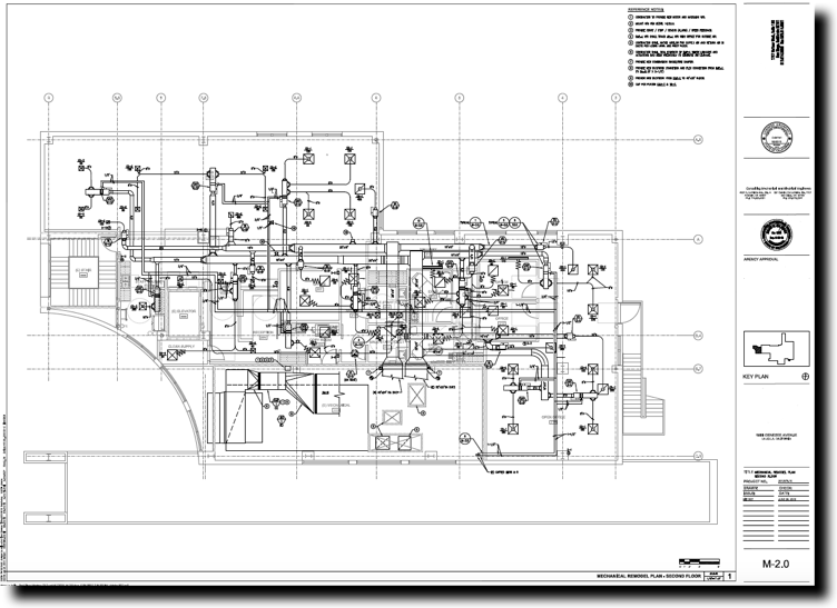
- “M” – Mechanical
- HVAC Sheet Metal
- HVAC Piping
- “E” – Electrical
- Power
- Lighting
- “P” – Plumbing
- “FP” – Fire Protection
Title Block
The main purpose of the title block is to identify the project and engineers involved in the design. Also included is a place for the individual responsible for the design and a date; a place to record the progression and date of any milestones such as a plan check set, addendums and their date. Title blocks can run horizontally along the bottom of the page or vertically along the right edge of the drawing. The title block should be visible when the drawings are rolled up, that way you can tell without having to unroll them which project it is related to.
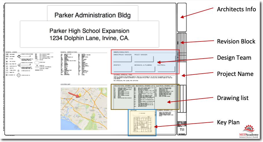
Revision Block will show any changes made to the drawings since they were issued. You might also find the original issue date and comments such as “Issued for Construction”. A revision number will be given that corresponds to clouded areas on the drawing where changes were made under this revision number.
Grading plan – shows the new and existing grading, the contour of the land.
Location map shows where the property is located on a Google map or other source.
Key Plan – this shows you where in the building the current drawing is located in reference to other sections of the building.
Site Plan (Plot Plan) – this shows how the building structure is situated on the plot of land it’s built upon. The site plan shows the contours, boundaries, roads, utilities, trees, structures, and other significant physical features on or near the construction site. It shows the locations of proposed structures in outline.
The site planshows the survey marks, including the bench mark (BM), with the elevations and the grading requirements. Surveyors use the plot plan shown below to set up the corners and perimeter of the building using batter boards and the line stakes. The plot plan furnishes the essential data for laying out the building.
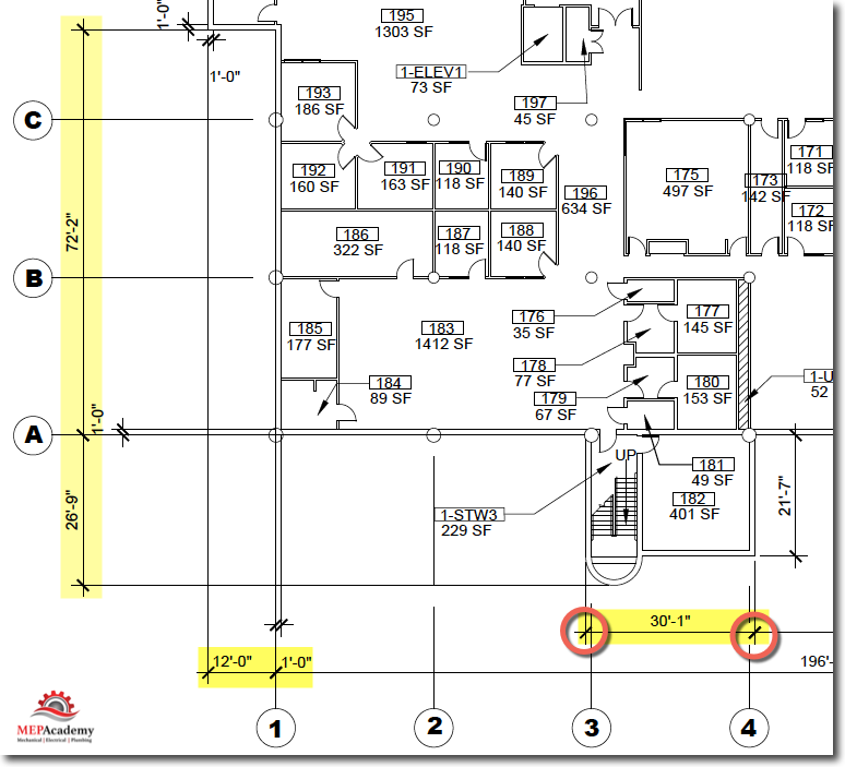
The yellow lines highlighted in the image below shows the property line, while the blue highlighted area shows the building area as it’s located on the property.
There will be a north arrow somewhere on the drawing providing the orientation of the building to North, this is especially important when doing heating and cooling loads. Depending on which hemisphere you’re in, this will determine which exposure get shade and how the sun hits various aspects of the structure, effecting its heat gain or loss. The north arrow is shown in the upper right hand corner of the below drawing.
The site plan is drawn at a small scale so that everything fits on one page including the property boundaries. As you can see in the example site plan below, the driveway is shown entering off of the roadway. A dimension is shown indicating how far each corner of the building is in relationship to the property line or boundary.
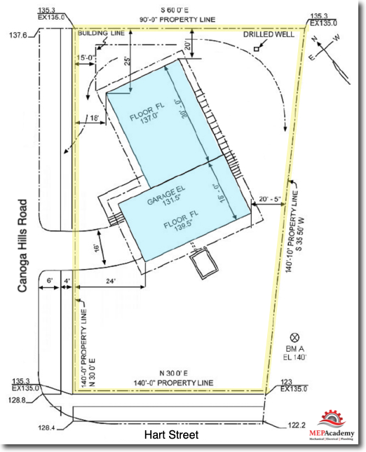
Another item of interest on the site plan is the building finished floor elevations for the garage and floor plan. The length of the properties boundaries are also shown.
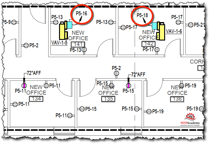
Electrical Drawings
You should be able to find all the HVAC equipment that requires electrical power on the electrical drawings. Shown below are two VAV’s (VAV 1-5 & VAV 1-6) that are provided with electrical power. You can read the description as circled in red as the electrical panel number and the circuit in that panel, such as; P5-16 (Panel 5, Circuit 16).This indicates that VAV 1-5 has electrical conduit and wire coming from panel 5 and circuit #16 in that panel.
Structural Drawings
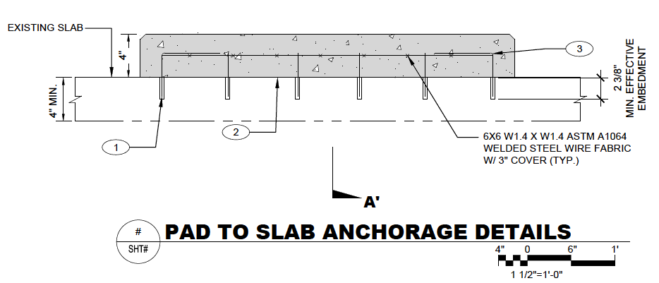
The structural engineer will design the support framing for the building in addition to miscellaneous equipment supports and concrete pads. They will do all of the calculations to ensure that the structure can support the various weights, wind loads, seismic activity and other stresses bearing on the building and its components. For the HVAC contractor this could include the design of special roof duct supports and equipment pads.
Below is a concrete pad designed by the structural engineer and shown as a detail on the structural drawings.
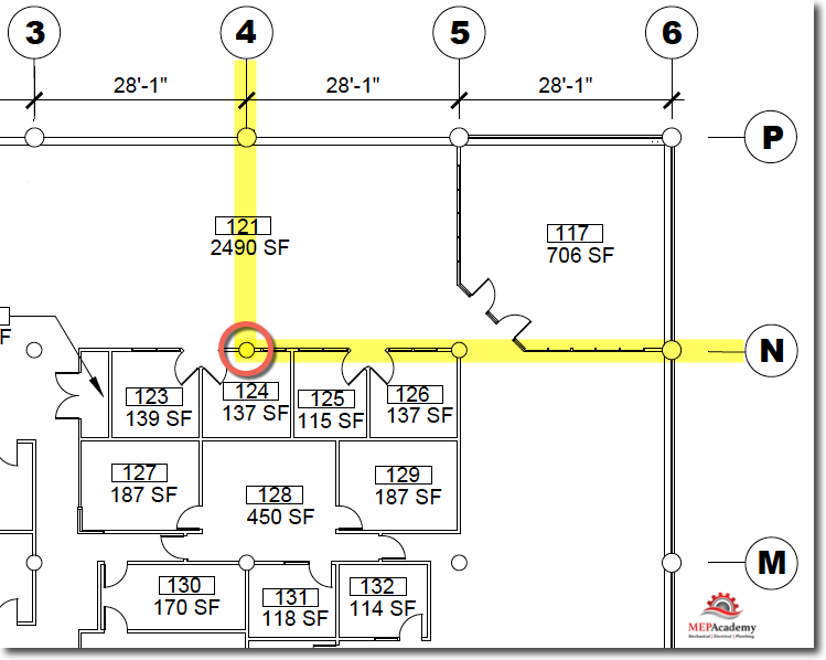
Column Lines
“Column lines help you find common areas on different floors.”
If you locate the intersection of column line “4” & “N” on the first floor, then you can find the same location directly above on the 2nd floor by finding the same column lines. This is helpful when trying to trace sheet metal, piping or utility risers that penetrate the floor.
Architectural, structural and all mechanical drawings should have the same column line references.
Dimension lines
Dimension lines are used to indicate the distance between two points.
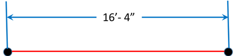
Dimension lines can be shown many different ways, such as shown here with arrows as end points or hash marks.
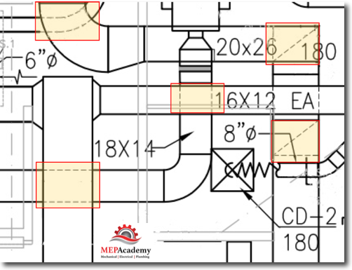
Hidden Lines
Hidden lines represent lines traveling under or on the inside of an object. These invisible portions of an item are often represented by dashed lines. Hidden Lines give an indication of items that are behind or below another item, as shown here highlighted in yellow. If you see dashed lines, those are part of a hidden item. The hidden items in this drawing show other sheet metal air ducts traveling under the duct above.
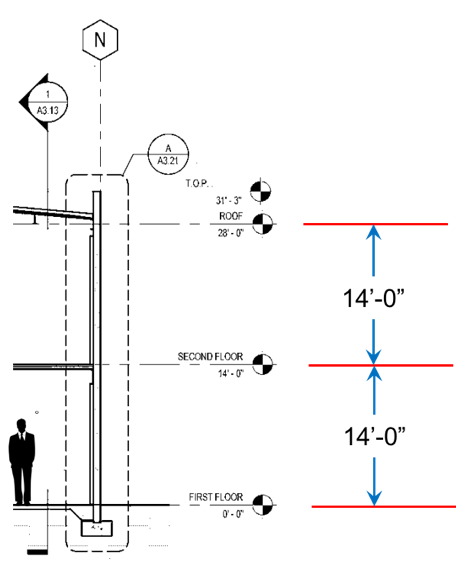
Elevation View
This is the view that shows the outside or inside of the building from a standing position, eyes forward.
Elevation views are used to determine sheet metal riser lengths.
Watch this Video for a quick overview of a complete set of Construction Drawings.
Now click the link below for Chapter #2 “Architectural Drawings” to get an overview of these drawings.
- Chapter #1 – General Layout of Drawings
- Chapter #2 – Architectural Drawings
- Chapter #3 – Plan, Elevation, Section Views and Details
- Chapter #4 – HVAC Mechanical Drawings
- Chapter #5 – Understanding HVAC Symbols
- Chapter #6 – Drawing Scales (How to Read Scales including Metric Scales)
- Chapter #7 – Sheet Metal Shop Drawings
