Chapter #2 – Architectural Drawings (How to Read Construction drawings)
You will need to understand how to read the Architectural drawings as they have information that can impact the cost of the Mechanical estimates. This section will cover some of the Architectural drawings and what to look for when bidding a Mechanical project. This section is not an extensive coverage of Architectural drawings, but is intended to provide you with the knowledge on what to look for when bidding the mechanical portion of the project.
Architectural Drawings
You should be able to understand how to read the basic information on the Architectural drawings as these drawings are the foundation upon which all the other trades are drawn. The Architect designs the building, while the structural engineer figures out how to support the design. The Architectural design set may include the following drawings.
- Cover Sheet
- General Notes, Drawing Index, Abbreviations, Code Info
- Plot Plan (site plan)
- Foundation Plan
- Floor Framing Plan
- Floor Plans
- Roof Plans
- Reflected Ceiling Plan
- Window and Door Schedules
- Wall Sections
- Elevation Plan
- Details and Section Views
Architectural Floor Plans
You can use the Architectural floor plans to identify the name and use of a room. The drawings will show the room layout with walls, doors and windows. Each room should be identified by a room number and room name.
If you’re not familiar with reading drawings then you’ll need to study the background carefully to discern the various ways in which building items are represented on the drawings. Just like in real life the first one or two letters of the room number will indicate the floor its located on, as in this example here all the room numbers begin with 1, so we can assume this is the first floor.
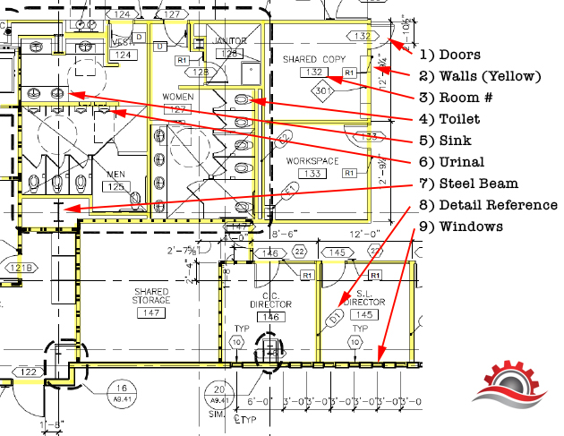
As can be seen in the above image of the bathroom area taken from the floor plan of an Architectural drawing, there are symbols for each of the bathroom fixture. We have highlighted all the walls in yellow to make it easier to see each room.
Reading a set of construction drawings requires that you learn basic drafting guidelines and the symbols used to convey meaning, much like a traffic sign tells you what to expect up ahead.
Reflected Ceiling Plan
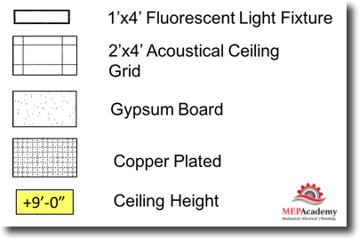
The reflected ceiling plan shows you what type of ceiling is used in each room. Below is an example of a small portion of a building, showing the type of ceiling used. With each set of architectural drawings there will be a legend for the ceiling types used in the set. (See legend below)
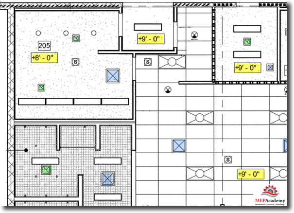
The below reflected ceiling plan identifies the type of ceiling, light fixtures used and the height (yellow highlight) of the ceiling in each room. Looking at the reflected ceiling plan above you can also see that Supply (blue highlight) and Exhaust (green highlight) grills are shown on the ceiling in addition to the lights.
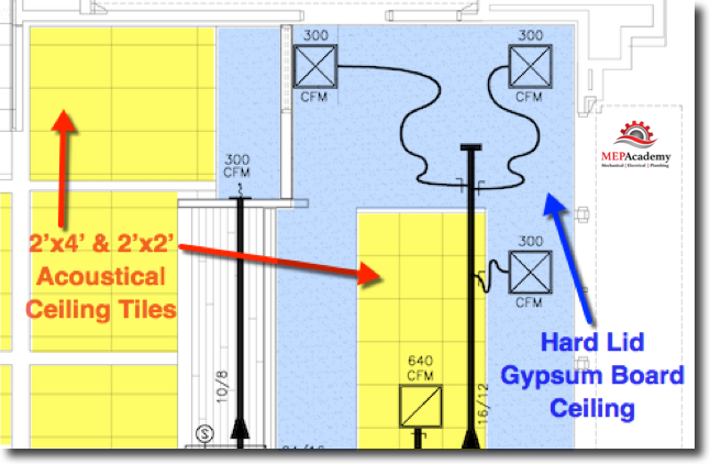
The HVAC system ductwork and air distribution grilles are overlaid on the reflected ceiling plan. By looking at the reflected ceiling plan below and the legend above you can identify the type of ceiling that each air distribution is set into.
For any volume damper hidden above a hard lid ceiling you will need a remote damper operator or an access panel to provide a means for adjusting the damper. The remote damper operator allows you to adjust the volume damper without needing to remove a piece of the ceiling (see Sheet Metal Specialties).
Fire Rated Corridors
In large commercial buildings you will often find that the corridors are fire rated to protect the occupants in case of a fire. There are several common methods of rating the emergency exit ways. Fire rated corridors are important to the HVAC industry because under certain circumstances when a supply, return or exhaust duct penetrates the fire rated assembly, which could be the wall or ceiling, a fire or fire/smoke damper could be required.
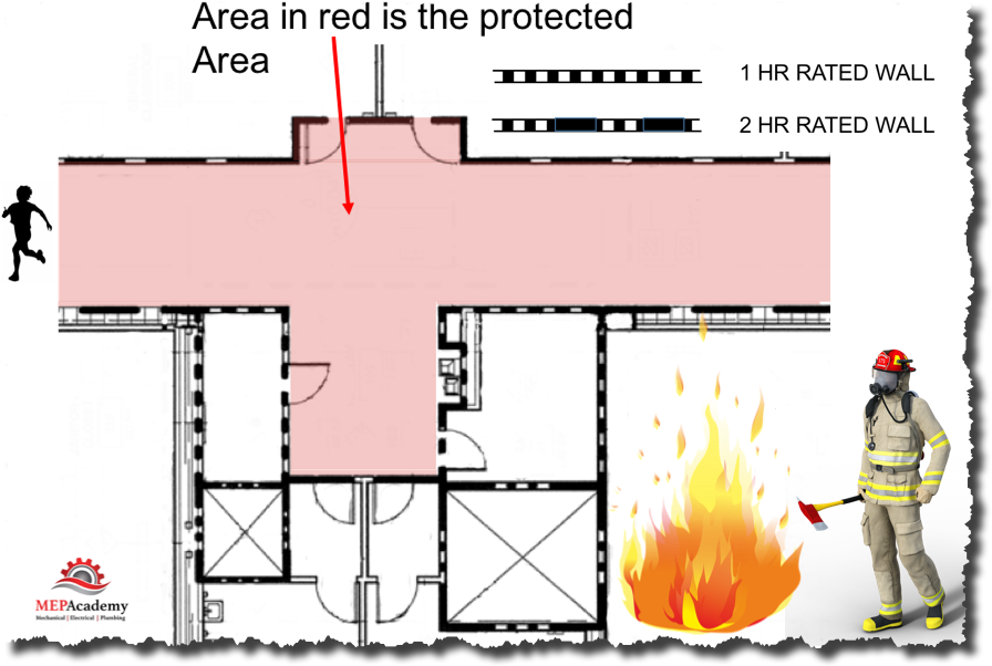
The corridor or emergency pathways are rated to allow sufficient time for the occupants to evacuate the building in the case of a fire. The rated corridor or pathway will prevent the fire from spreading long enough for the occupants to get out. The area shown in red above is the emergency pathway or corridor that is fire rated.
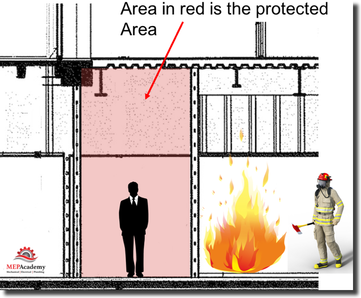
Fire Rated – Slab to Slab System
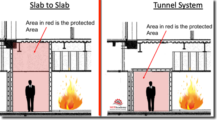
In this method of fire rating the exit way, the use of rated walls extending from the floor all the way to the deck above provide protection. There is no rated ceiling, as the deck above is considered a fire barrier.
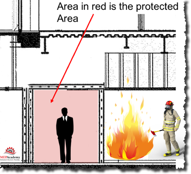
Fire Rated – Tunnel System
This version of a fire rated exit way is constructed in a tunnel configuration that’s fire rated for the purpose of protecting the occupants during an emergency situation. With the tunnel rated system if you penetrate the rated tunnel ceiling to install a supply, return or exhaust grille you will be required to install a fire damper or a fire/smoke damper to maintain the fire rated construction.
Here are the two most common fire rated construction methods side by side for comparison.
Detail Drawings
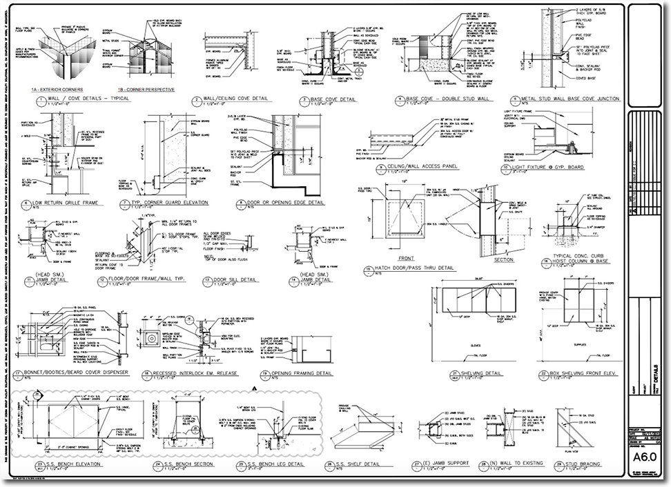
In order to show how certain aspects of the construction is to be built in greater detail each trade will provide a detail drawing. These drawings show various components of construction in greater detail. This allows the installers a more accurate detail of what the engineer expects in the way of material and methods in a visual format as opposed to the specifications.
Now click the link below for Chapter #3 “Plan, Elevation, Section Views and Details” to get an overview of these drawings.
- Chapter #1 – General Layout of Drawings
- Chapter #2 – Architectural Drawings
- Chapter #3 – Plan, Elevation, Section Views and Details
- Chapter #4 – HVAC Mechanical Drawings
- Chapter #5 – Understanding HVAC Symbols
- Chapter #6 – Drawing Scales (How to Read Scales including Metric Scales)
- Chapter #7 – Sheet Metal Shop Drawings


