Saturday, June 14, 2025
Home Blog

Refrigeration Technicians Best Tools

0
List of Refrigerant Technician Tools

Essential Tools for Every Refrigeration Technician: A Comprehensive Review

Are you intrigued by the inner workings of refrigeration systems and the vital role they play in our everyday lives? Whether you’re an aspiring refrigeration technician or a seasoned pro, understanding the tools of the trade is essential.

In this comprehensive review, we delve into the top tools that every refrigeration mechanic should have in their arsenal. These tools are not mere conveniences; they are the very instruments that empower technicians to diagnose, repair, and maintain refrigeration systems efficiently and effectively.

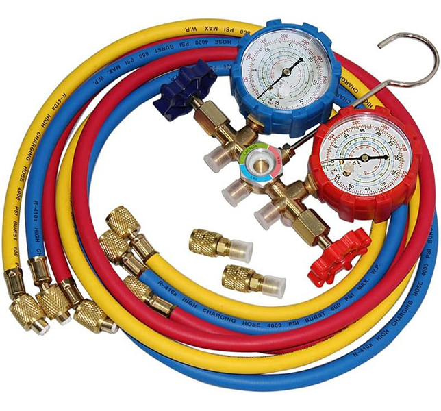
1. Manifold Gauge Set: Refrigeration mechanics rely on manifold gauge sets to simultaneously measure high and low side pressures in refrigeration systems. These sets are like the eyes of the technician, providing critical insights into the system’s condition. By providing real-time data, refrigerant gauges are essential for diagnosing issues and ensuring optimal system performance.

List of Gauge Manifolds

1- Shikha 5 Foot (see image)

2- Fieldpiece SM380V

3- Testo 550’s

4- Lichamp Gauge Set

5- Yellow Jacket 42004

2. Vacuum Pump: A vacuum pump may seem unassuming, but its role is monumental. It evacuates air and moisture from refrigeration systems before the introduction of refrigerant, ensuring that the system operates efficiently without unwanted contaminants.
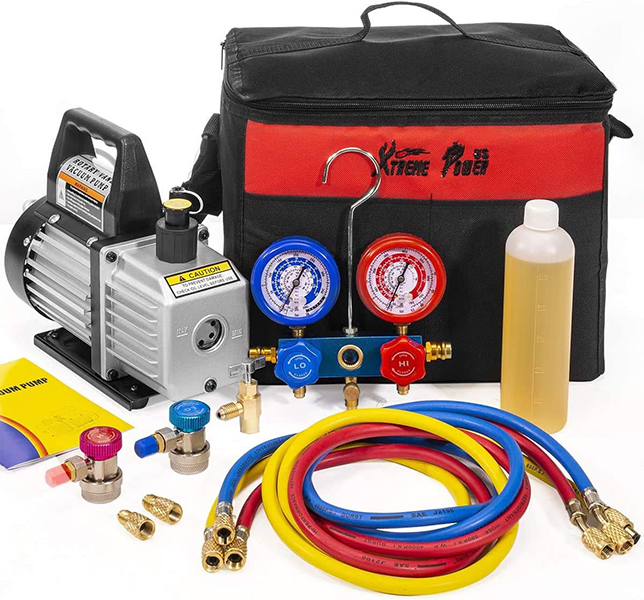
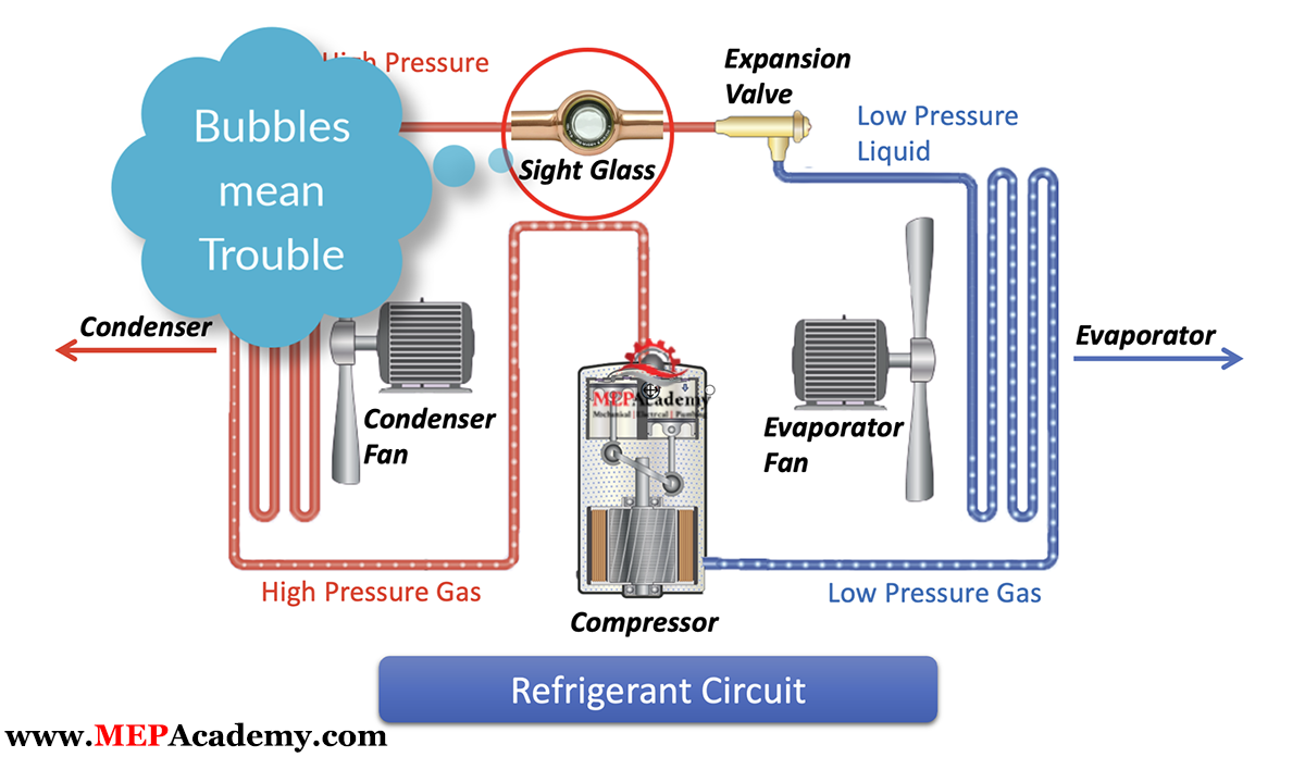
3. Leak Detection Tools: Finding elusive refrigerant leaks is a challenge without the right tools. Leak detection tools, including electronic detectors and bubble solutions, play a crucial role in environmental protection and system efficiency by pinpointing these leaks.
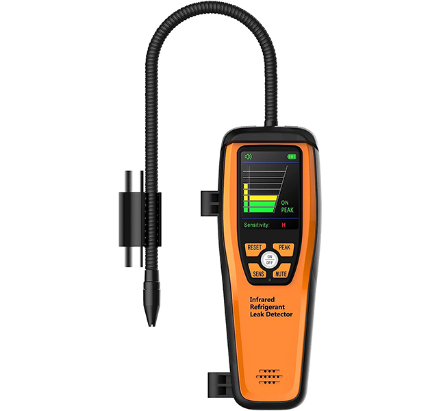
4. Digital Multimeter: An HVACR technician’s electrical diagnostic prowess relies heavily on a digital multimeter. This tool measures voltage, current, and resistance in electrical components, making it indispensable for troubleshooting electrical issues.

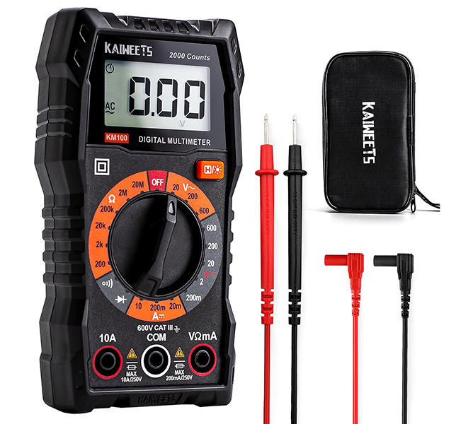
List of Digital Multimeters

1- KAIWEETS Digital Multimeter (see image)

2- AstroAI TRMS 6000

3- AstroAI 4000

4- Astro 2000

5- Klein MM325

5. Pipe Cutters and Flaring Tools: Copper pipes are the lifeblood of many refrigeration systems, and pipe cutters and flaring tools ensure these essential components are accurately cut and shaped for the job.
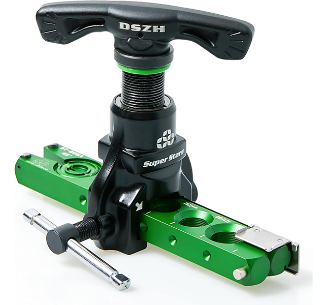
6. Pipe Benders: The importance of smooth, kink-free bends in copper pipes cannot be overstated. Pipe benders are the secret to achieving these precise bends without compromising the integrity of the pipe.

7. Thermometers and Thermocouples: When it comes to temperature measurement, accuracy is key. Thermometers and thermocouples help technicians monitor temperatures at various points in the system, assisting in both diagnostics and cooling optimization.

8. Tubing Tools: Properly preparing tubing for installation is a fundamental step in any refrigeration project. Tubing tools, such as deburrers and reamers, ensure that tubing is ready for action.

9. Hex Key Set: Hexagonal screws and bolts are commonplace in refrigeration systems. A set of hex keys is a technician’s trusty companion for swiftly disassembling and reassembling components.

10. Oil Pump and Oil Injector: Lubricating oil is the lifeblood of compressors. Oil pumps and injectors ensure that the compressor functions optimally by delivering the right amount of lubrication.

11. Torque Wrench: Precision matters in refrigeration systems. Torque wrenches guarantee that bolts and nuts are tightened to precise specifications, safeguarding components and maintaining proper seals.

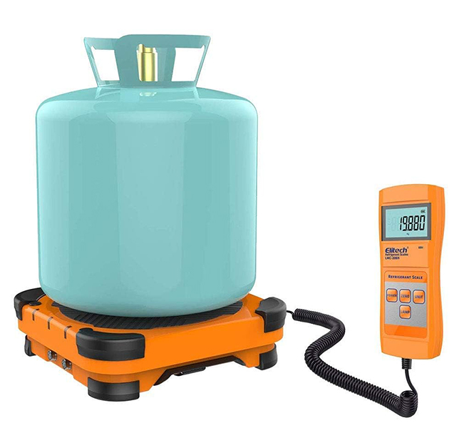
12. Digital Scale: In the intricate world of refrigeration, precision is paramount. This is where a digital scale steps in as a silent but indispensable partner for refrigeration mechanics. Why? Because refrigerants, lubricants, and various chemicals must be added to systems with meticulous accuracy.

A digital scale ensures that the right quantities are added, helping maintain the system’s efficiency, performance, and, perhaps most importantly, the environment. It’s not just about getting the job done; it’s about getting it done right, and that’s where the digital scale shines. So, let’s weigh in on the importance of this often-overlooked tool in the refrigeration technician’s toolkit.

List of Digital Scales

1- Eiltech LMC-200A (see image)

2- Xetron High Accuracy

3- Eiltech LMC-300A

4- Yellow Jacket 68862

5- VIVOHOME Precision Electronic

These tools are the cornerstone of any refrigeration technician’s toolkit. Stay tuned as we dive deeper into each of these essential instruments, unveiling the art and science behind their usage, and why they’re indispensable for refrigeration technicians around the globe.

Air Filters vs COVID-19

0
Air filters vs COVID-19

In this article we’ll answer a question that we get all the time. What filter, if any, can filter out the SARS-CoV-2 virus which leads to COVID-19, the disease? We’ll show you how efficient the different air filters are at filtering out various items for asthma and allergy sufferers, and the virus that leads to COVID-19.

If you prefer to watch the Video of this presentation, then scroll to the bottom or click on the following link. Air Filters vs COVID-19

The ability of an air filter to remove microorganism, dust, pollen, dust mites, mold spores, pet dander, bacteria and viruses is indicated by a numerical value. This number, which is indicated as a MERV rating, states the filter’s efficiency at removing various sizes of these items. We’ll show you which filters, if any, work the best to protect you from these potentially harmful organisms. 

MERV Rating

Minimum Efficiency Reporting Values, or MERVs, indicate the filter’s ability to capture larger particles, those 0.3 microns and larger. The higher the numerical rating, the greater the air filter is at removing particles from the air stream. A MERV-13 is better than a MERV-11 filter at removing particles, but how good are they against bacteria and a very small virus that leads to COVID-19.

Virus and Bacteria Removal

According to ASHRAE, research has shown that the particle size of the SARS-CoV-2 virus that leads to COVID-19 is around 0.1 microns. This is much smaller than what may be picked up by these air filters. As this chart shows, the virus lives in the invisible region, while others like dust, cat dander and human hair are visible to the human eye. 

Sizes of various items shown in Microns. Invisible items in black area on chart, including the SARS-CoV-2 Virus.

Luckily, the SARS-CoV-2 virus doesn’t travel through the air own its own. It rides on respiratory droplets and droplet nuclei (dried respiratory droplets) that are predominately 1 micron in size and larger. These filters have various efficiencies at capturing the viruses that are in the 1-to-3-micron range according to ASHRAE.

The SARS-CoV-2 virus riding a respiratory droplet in the 1 to 3 micron range

ASHRAE

As the chart shows, ASHRAE recommends using a minimum of a MERV 13 filter, which is at least 85% efficient at capturing particles in the 1 to 3-micron size range. A MERV 14 filter is at least 90% efficient at capturing those same particles. High-efficiency particulate air (HEPA) filters are even more efficient at filtering human-generated infectious aerosols. 

MERV Rating and Air Filter Efficiency for Particle sizes 1 to 3 microns in size

By definition, a HEPA air filter must be at least 99.97% efficient at capturing particles 0.3 micron in size. This 0.3-micron particle approximates the most penetrating particle size (MPPS) through the filter.  HEPA filters are even more efficient at capturing particles larger AND smaller than the MPPS. Thus, HEPA air filters are more than 99.97% efficient at capturing airborne viral particles associated with SARS-CoV-2 which leads to COVID-19.

Checkout these HEPA Filters for your Home or Office

HEPA filters can capture and trap microorganisms, including viruses and bacteria, helping to reduce the risk of respiratory infections. So, if possible, use the highest MERV rated air filter with your system, or get a portable HEPA air filter for your room or office. HEPA filters are the most efficient at capturing small microorganisms like the SARS-CoV-2 virus.

Where are HEPA Filters used?

HEPA air filters are used in residential, commercial, and industrial facilities. In homes there are portable types that can be moved from room to room, and others that can be installed in a central air conditioning system serving the whole house. 

HEPA air filters are also used along with ULPA filters in cleanrooms, labs, and other spaces requiring a very clean environment.

Asthma and Allergy Management

For individuals with asthma, HEPA filters help reduce asthma triggers like airborne irritants and respiratory allergens. According to the Asthma and Allergy Foundation of America (AAFA), nearly 26 million people have asthma in the United States. There are 4.8 million children under the age of 18, and nearly 21 million adults suffering from asthma. On average, 10 people in the unites States die every day from asthma. A total of 3,517 deaths in 2021.

According to the AAFA over 100 million people each year in the United States experience various types of allergies. Allergies are the sixth leading cause of chronic illness in the U.S. HEPA filters are highly effective at removing allergens such as pollen, dust mites, and pet dander, providing relief to allergy sufferers. 

Editorial Process:

Some of the links in this article may be affiliate links, which can provide compensation to the MEPAcademy at no cost to you if you decide to purchase. Our reviews and articles are made by an industry professional experienced in the engineering and construction of commercial buildings.

Air Filters vs COVID-19

HVAC Equipment Cost Database

0
HVAC Equipment Cost Database

Are you paying too much for your HVAC equipment? How do you know if the quote you received for your equipment is a fair price? Do you have a method of comparing what you have paid for various HVAC equipment with what is being quoted currently?

Keeping track of the cost of HVAC Equipment allows you to quickly provide budgets and check the cost of equipment before you purchase. This database allows you to easily keep track of the most common HVAC equipment.

HVAC Equipment Cost Database

Using an HVAC Equipment cost database will save you a lot of money by avoiding the costly mistake of paying too much for equipment.

Air Conditioners price per ton and price per square feet historical equipment pricing database
Air Conditioners in Historical Pricing HVAC Equipment Database

Get your copy here. HVAC Equipment Cost Database

The HVAC Equipment Cost database keeps track of all your equipment quotes or purchases for easy reference and parametric checks, such as cost per ton ($/Ton), cost per CFM ($/CFM)

Only $199

HVAC Piping Unit Pricing

0
HVAC Piping Unit Pricing MEP Academy

For an HVAC Piping Estimators the need for quick budgets for the installation of piping is best handled with a spreadsheet of different material types and sizes. Having an estimating software program can make this process a lot easier, as the material pricing is always up to date and can be entered into the spreadsheet quickly. You can get a copy of this spreadsheet to help you price piping fast and efficiently.

HVAC Piping Unit Pricing Table
HVAC Piping Unit Pricing Calculator

HVAC PIPING UNIT PRICING 

Often the requirements of the RFP or bidding instructions will call for the price per foot to install piping beyond that which is required by the contract drawings. Such pricing maybe used for change-orders. Having these numbers available and updated often also gives you a quick reference for budgeting projects. It’s good to know when doing job site comparisons of different piping options or during discussions with engineering, what the cost is for the various piping sizes and types of materials. 

HVAC Piping Unit Pricing Calculator for Copper and Carbon Steel from 1/2" to 14"
HVAC Piping Unit Pricing Calculator for Copper and Carbon Steel from 1/2″ to 14″

COST PER FOOT

The cost per foot for the installation of piping needs to include fittings and hangers prorated into the value. It’s best to look at a standard length of pipe and then figure that you will have a Tee and 90 degree elbow in that length.

So for example, using twenty feet of copper water pipe with a Tee and 90 degree elbow plus the hangers to build a unit price would represent a field condition of a fitting every ten feet.

For higher density projects like Hospitals you could put more fittings in your unit pricing. Total those cost up and then divide by 20 to derive at a cost per foot for that particular size and material type.

20 feet of pipe + 2 Fittings + 3 Hangers / 20 = Cost per Foot

If the piping is insulated, you can also put the values in for insulation.

The Estimating Wizard provides two spreadsheets for tracking unit pricing, one for HVAC Piping and the other for Plumbing piping. Get a copy and start tracking your cost per foot, or be prepared to give a quick budget based on your knowledge from your spreadsheet of unit prices. Watch the video below to see how quick and easy it is to track the cost per foot for various sizes and material types. 

MEP Academy HVAC Piping Unit Pricing Spreadsheet

The MEP Academy provides a spreadsheet that makes calculating unit pricing simple. The spreadsheet is available by following this link, HVAC Piping Unit Pricing Spreadsheet

HVAC Piping Unit Pricing Calculator Example

In the screenshot above there is a place for you to build your hanger requirements (#1), and a place to put your tax rate and hourly labor rate (#2).

For each size of pipe and material type you would insert the unit cost for Material (#3) and Labor (#4).

Under item (#5) you would build your typical run of pipe and enter the quantity of fittings you might expect for the type of building and system. You would add whatever you think will be required for every so many feet of pipe. In the example above we are showing that for every 20 feet of pipe you will have 1 Elbow and 1 Reducing Tee.

Under item (#6) you would add the cost per lineal foot for insulation if required. You could also look at insulation as a separate value and leave the pipe bare.

Line item (#7) is where you indicate the hanger spacing, and for each hanger you defined under item (#1) you will get the quantity as defined by the linear feet in item (#5) divided by your hanger spacing, which will affect your cost.

Line item (#8) is the calculated cost per linear foot of piping for that size and material type of pipe.

Summary Sheet

After you have all your unit pricing information inputted into the spreadsheet, all you have to do to get a budget for installing piping is to enter the quantity of piping (#9) for each size and material type (#10). The system will automatically calculate the cost (#11) to install that run of piping based on your unit pricing data. The total cost will be shown at the top of the spreadsheet (#12).

Piping Unit Pricing Calculator Summary Page

You can get your copy here. HVAC Piping Unit Pricing Spreadsheet

AC Condensate Drain Sizing and Layout

0
Condensate drain pipe design and layout

The proper sizing and layout of condensate drain lines is important for the protection of property and for the proper functioning of the air conditioning equipment.

If you prefer to watch our YouTube version of this presentation, scroll to the bottom.

Condensate Drain Pipe Sizing

The size required for the condensate pipe is dictated by the local code. Enclosed you will find the requirements for many local codes, but be sure to check your code for your local requirements. If the outlet size of the equipment’s condensate drain is larger than what’s shown in this chart then your required to use the larger outlet size.

Minimum Condensate Drain Pipe Sizing Chart

Slope to be at least 1/8” per foot or 1 percent, that is for every 12” horizontally there must be at least an 1/8” drop vertically. 

Condensate drain piping to slope a minimum of 1/8" per every 12" horizontal
Condensate drain piping to slope a minimum of 1/8″ per every 12″ horizontal

Attics or Furred Spaces

If the Air Conditioner is suspended above an inaccessible ceiling, such as a gypsum board ceiling or attic space then you will need to provide a means for protecting the building elements from the overflow of the primary drain and for indicating that there is a leak.

Also, drain pans that are poorly drained can cause water to stay in the pan risking the possibility of algae and bacteria growth. Below are some possible solutions, but as always check your local code for the approved method.

  • Option 1 – Secondary drain pan with drain piping. This would hang below the Air Conditioning unit in case the A/C units primary pan overflowed. Also, there is a requirement to provide secondary drain piping to a point of termination that would provide notification to the occupants that there is a leak, such as terminating above a window or doorway.
Option 1 - Secondary drain pan with piping terminating in observable location
Option 1 – Secondary drain pan with piping terminating in observable location

  • Option 2 – An additional drain pipe connection that sits above the primary drain connection and whereby the secondary drain piping terminates in a location to alert the occupants of the clogged primary drain.
Option 2 - Secondary drain piping connection to primary drain pan
Option 2 – Secondary drain piping connection to primary drain pan

  • Option 3 – Leak detection device that automatically shuts down the Air Conditioner if the primary drain becomes clogged.
Option 3 - Primary drain with leak detection device
Option 3 – Primary drain with leak detection device

  • Option 4 – Secondary drain pan with leak detection, located beneath the coil that shuts down the unit upon a leak.
Option 4 - Secondary drain pan with leak detection
Option 4 – Secondary drain pan with leak detection

The additional drain pan or drain pan connection shall be provided with a drain pipe that will determinate in an observable area, such as in front a window or above a doorway, and be of a size not less than 3/4”. Secondary drain pan shall not be less than 1-1/2” in height and extend 3” wider on each side of the coil or AC unit.

Secondary drain piping terminating above window. Pipe doesn't have to be visible as shown.
Secondary drain piping terminating above window. Pipe doesn’t have to be visible as shown.

Drain Termination 

Where can and can’t you terminate the air conditioners condensate drain piping? There are several options where you can terminate the condensate drain line;

  • Indirect Drain
  • Condensate Pump to Indirect Drain
  • Drywell
  • Leach pits
  • Landscaped areas that are properly designed to handle the volume of condensate
  • To Properly designed stormwater treatment systems. 

Indirect Drain

  • Lavatory tailpiece in the same tenant space as the air conditioner
  • Laundry standpipe
  • Janitors Sink
  • Inlet of Bathtub Overflow – Must be accessible
  • Collect and send to cooling tower (See description below)
Cooling Coil condensate to sink tailpiece.

The connection to a plumbing fixtures tailpiece has to be made within the same tenant space as the air conditioner cooling coil that is generating the condensate.

Drywell

A drywell can be used for the termination of your air conditioners condensate drain. Check your local code for the specifics, but generally it includes some or all of the following depending on whether it’s for residential or a commercial project:

  1. A minimum size hole, such as 2 foot by 2 foot by 3 feet deep, or a round hole such as 12” diameter by 3 feet deep.
  2. A minimum of 6” of soil or concrete shall provide cover above the rocks
  3. Some form of barrier between the soil and the top of the drywell where the rock begins, such as building paper or plastic
  4. Drywell to be filled with gravel or crushed rock, often with a stated minimum size rock such as 1 inch diameter
  5. The termination of the condensate drain pipe shall connect indirectly to the drywell drain pipe.
  6. The drywell drain pipe to be a minimum of 1-1/2” PVC or other approved material.
  7. Drywell to be at least three feet away from the building structure or any footings.
Drywall for Air Conditioner Cooling Coil Condensate

There are various methods of providing drywells depending on the local code. There are prefabricated drywells that can be used and ones that are made by using a large diameter piece of PVC pipe or similar material.

Some codes will require you to collect the condensate from cooling coil drain pans and return it to the cooling tower if the equipment is served by a cooling tower and the total combined capacity of the HVAC cooling coils exceeds a certain amount like 65,000 btu/hr.

This is a water conservation measure, and there are some exceptions to this requirement, such as if the total capacity of the AC Equipment cooling coils are less than 10% of the total capacity of the cooling tower, or if the location of those AC Cooling coils are in a remote location, far from the tower.

Some locations where you can’t terminate condensate;

  • Public ways
  • Sidewalks
  • Driveways
  • Alleys
No termination of condensate on public area ways

Excluded from Code Requirements

Excluded from these codes are non-condensing type of equipment like radiant cooling panels that are designed to prevent condensate from occurring by keeping the temperature of the chilled water above the dew point temperature/vapor pressure of the surrounding air. These are system designed to operate in sensible cooling only modes.

Piping Material

The material types that can be used for condensate drain piping varies by jurisdiction but the most commonly cited materials are: 

  • Copper
  • PVC – DWV
  • CPVC
  • ABS – DWV
  • Polyethylene
  • Galvanized steel
  • Cast iron.

Also the use of short radius 90-degree elbows are often prohibited. You can normally use standard fittings until you reach a certain size at which point you might be required to use drainage pattern fittings (DWV)

Traps

Traps are to be installed as required per the manufactures recommendation. No traps are required on the secondary drain pan, this is to allow immediate notification that the primary drain has failed.

Cleanouts

Cleanouts are required in case of plugged drain pipes. Provide as required to prevent the need to cut drain pipes for unplugging. Some of the following maybe used for cleanouts if approved by your local code authority;

  • Plugged tees
  • Union connections
  • Short clamped hoses at the unit (see image above)

When you have more than one air conditioning unit condensate tied to a main condensate pipe, then every change of direction shall have some method of cleanout. Check your local code as this maybe a requirement for even a single air conditioners condensate piping.

Condensate Pumps

Condensate pumps can be used to elevate the condensate vertically to a point where it will then discharge into a code approved gravity sloping condensate drain line. The condensate pump should be interlocked with the Air Conditioning Unit to prevent its operations if the condensate pump is inoperable. 

Checkout these Condensate Pumps

Please remember that code requirements are always changing, so check for the most current code in your area at the time of design and installation. Or ask an inspector for the current installation practice.

Refrigerant Line Sets

Video of this Article

MEP Academy Estimating Spreadsheet

0
Sheet Metal, Piping & Plumbing Estimating Spreadsheet

Having an MEP Academy Estimating Spreadsheet that automates portions of your estimates, will save you valuable time that could be used to make more sales. All aspects of the cost of furnishing and installing an HVAC and/or a Plumbing system is contained in one spreadsheet made specifically for the MEP industry. For plumbing only see below.

For a Plumbing only Spreadsheet, use this Commercial & Residential Version. Plumbing Only. For a simple Residential HVAC & Plumbing Spreadsheet. Residential version.

Dashboard

The Main Dashboard provides you with all the information you need to make a quick decision on whether to make further adjustments, or if one of the metrics looks out of place based on historical data. The Dashboard gives you a quick overview of all that is going on within the Estimating Spreadsheet.

Estimating Dashboard within the MEP Academy Estimating Spreadsheet

Your MEP Academy Estimating Spreadsheet needs to be able to handle rental equipment, general conditions, subcontractors, piping and plumbing takeoffs, sheet metal, labor rate tables with crew mix capabilities, , and a bid summary. Each sheet in the estimating spreadsheet automatically calculates the values you enter, showing you a new total bid amount.

Will cover portions of the MEP Academy Estimating Spreadsheet starting at the back of the Excel spreadsheet and working our way toward the front summary page last.

Labor Rate & Crew Mix Table

Choose your crew mix based on the level of experience and the different pay scales based on each project. Pick any combination and quantity of tradesman based on the requirements of the project. 

Labor Rates and Crew Size within the MEP Academy Estimating Spreadsheet

There is a separate crew labor rate for HVAC Piping Shop & Field, Sheet Metal Shop & Field, and Plumbing.

Labor Crew Size and Labor Rate

HVAC & Plumbing Equipment

Enter the project equipment price and labor to rig the HVAC and Plumbing equipment into place. Compare supplier pricing easily side by side. The MEP Academy Estimating Spreadsheet automatically selects the lowest bidder but lets you override that decision.

HVAC Equipment page within the Estimating Spreadsheet
HVAC & Plumbing Equipment Sheets

General Conditions

Do you need a jobsite trailer or onsite management? Enter the quantity and level of the staff required to run the project, whether one person or dozens. Set the quantity and duration of each general condition, along with the rate. General Conditions is broken down into three sections as follows: #1 – Management, #2 – Construction Office (Non-Reoccurring Expenses), and #3 – Construction Office (Reoccurring Expenses).

General Conditions in Estimate
General Conditions in Estimate Spreadsheet

HVAC & Plumbing Subcontractors

HVAC & Plumbing contractors often subcontract out for Air & Water Balance, Sheet Metal & Piping Insulation, Water Treatment, Building Automation, Excavation and other specialty trades that they don’t self-perform. This spreadsheet was made especially for the HVAC & Plumbing contractor and their most often used subcontractors.

Subcontractors – Rentals – GC’s – Engineering Pages
Subcontractors Page in Spreadsheet

Plumbing Fixtures

For those contractors that do plumbing the following Plumbing Fixture sheet will give you a place to record your vendors quotes and the labor it takes to install each type of fixture. What is also revealed is the overall cost per fixture.

Plumbing Fixtures page within the Estimating Spreadsheet
Plumbing Fixtures

MEP Specialty Sheets

Each trade has a specialty sheet for those items that aren’t considered equipment or a fixture, but for which there is a cost impact. The MEP Academy Estimating Spreadsheet includes Sheet Metal, HVAC Piping & Plumbing Specialty sheets.

HVAC and Plumbing Specialty Pages within the Estimating Spreadsheet
Specialty Sheet In Estimating Spreadsheet
Specialty Sheets in Estimate Spreadsheet

Material & Labor Summary Sheets

You will find a Sheet Metal, HVAC Piping & Plumbing material & labor summary sheets where all of the other specialty sheets are summarized for your review and last minute edits. Each sheet will be divided between field & shop fabrication work. The first section covers the field installation items.

Sheet Metal Material and Labor Summary – Estimating Spreadsheet

Field Summary Section

This is where you will put your material takeoff information for the following:

  • Rectangular & Round Ductwork
  • HVAC Piping
  • Plumbing Piping

This is also where the other sheets that you filled out will be summarized, such as the following;

  • HVAC & Plumbing Specialties
  • HVAC & Plumbing Equipment Labor
  • Plumbing Fixtures
Material & Labor Summary Sheet in Estimating Spreadsheet
Material and Labor Summaries

Each of the field labor summary sheets contain a row to add for the following

  • Material Handling
  • Consumables
  • Punch List
  • Cleanup
  • Detailing
  • Supervision

Shop Fabrication Summary Section

For those of you that have a fabrication shop, there is a section to add material and labor.

Shop Fabrication Summary

Rentals

For those HVAC air conditioning and Plumbing projects that require a crane, fork lift, scissor lift or any other equipment that you don’t own but will be required on the project. Having a spreadsheet that maintains a list of the most common equipment you normally rent along with their rental rate will save you time and money while avoiding having to call for pricing on every job.

Rental Sheet in Estimating Spreadsheet

Engineering

If you do your own design then you should have a sheet of each of the personnel responsible for spending time on the engineering task. If you’re doing design/build work, but don’t do the engineering yourself, but hire a third party, then you should add some engineering review time. It’s your responsibility to manage your third-party engineer to make sure they design within your cost parameters.

Engineering Cost
Engineering Cost Tab in Estimating Spreadsheet

Estimate Summary

All of your estimates are summarized on the last tab of the  MEP Academy Estimating Spreadsheet for easy review. You can quickly scan each of the categories to see where all the project cost has shown up. There is the labor and material summary for HVAC Sheet Metal, HVAC Piping, and Plumbing and another section for Subcontractors, General Conditions, Rentals, etc.

Estimating Spreadsheet Summary Page
Estimating Summary
MEP Academy Estimating Spreadsheet Summary

Bid Risk Assessment Form

The MEP Academy Estimating Spreadsheet contains a bid risk assessment form that rates the success of winning any particular project that you are contemplating pursuing. The risk assessment form will help you determine if the project is worth bidding based on a set of questions that rate your answers.

Bid Risk Assessment Form
Bid Risk Assessment

The answers to these questions will give you a score from which you can use to see how the project rates on a scale of risk and reward. The total risk assessment score will also inform you which level of approval is required within your company depending on how you rate your risk values as the example shown below. The total score is 25, which according to this contractor would require the Vice President to sign-off on the project or approve the decision to pursue bidding on the project.

Bid Risk Assessment Score

MEP Academy Estimating Spreadsheet Summary

The MEP Academy Estimating Spreadsheet is used to gather all the information for estimating a project, putting it into a format where you can make quick adjustments and decisions while the spreadsheet gives you an immediate update on the price.

Purchase this spreadsheet at its currently reduced price of ONLY $245.00, which usually sells for $599.00

Watch the YouTube video below to see the MEP Academy Estimating Spreadsheet in action.

Buy Now for ONLY $245

What is Flash Gas in a Refrigeration System

0
Flash gas in Refrigerant System

Have you ever wondered what flash gas really is in a refrigeration system? It’s a common term, but rarely explained clearly — and understanding it is key to troubleshooting and system design. In this article, we’re breaking it down in simple terms, with visual diagrams so it finally clicks.


Flash Gas Explained – Refrigeration Basics Made Simple


Flash gas is the portion of a refrigerant that instantly boils — or ‘flashes’ — into a vapor when it experiences a sudden pressure drop.

It most often occurs at two critical places in the refrigeration cycle:

  1. At the expansion valve outlet, and
  2. In the liquid line, if the system isn’t charged or sized correctly.


Here’s the science: When high-pressure liquid refrigerant exits the metering device and enters the evaporator at a much lower pressure, it can’t stay in liquid form. The drop in pressure causes part of the refrigerant to boil instantly, absorbing heat in the process. That’s flash gas.

But… flash gas can also form where it shouldn’t — in the liquid line — if the refrigerant pressure drops too early. That’s a red flag.

Bubbles in the sight glass means trouble

Here on the liquid line, just before the expansion valve, you’ll notice the sight glass. This is a critical inspection point for technicians. When the system is running properly, the sight glass should show a clear, full column of liquid refrigerant — no bubbles. If you see bubbles or foam here, it could indicate flash gas in the liquid line, often caused by a low refrigerant charge, loss of subcooling, or excessive heat gain in the line. Always remember: clear sight glass, healthy system; bubbles mean trouble.


In the evaporator, flash gas is expected — it’s part of the process. But in the liquid line, it’s a big issue.

Flash gas before the metering device reduces cooling capacity and causes erratic operation. You’ll see:

Poor superheat control. Compressor noise. Bubbles in the sight glass

How to Prevent Flash Gas

To prevent flash gas where it shouldn’t be, follow these best practices:

  1. Ensure proper refrigerant charge
  2. Insulate long liquid lines in hot environments
  3. Keep condensing pressures within design range
  4. Use subcooling to your advantage. See our other video on superheat and subcooling for a further explanation.

Subcooling is key! It ensures the refrigerant stays a liquid until it reaches the expansion device.


So to recap — flash gas is normal in the evaporator, but not in the liquid line. Understand it, control it, and your refrigeration system will thank you.

Proper Heat Pump Sizing for Summer Cooling

0
Heat Pump Sizing
Heat Pump Sizing

In HVAC, there’s one decision that drives system performance, customer comfort, and your bottom line and thats proper heat pump sizing for summer cooling. Yet even today, improper heat pump sizing remains one of the biggest mistakes in the industry.

Oversized systems short cycle, fail to dehumidify, and lead to early equipment failures. Undersized systems run constantly, burn energy, and can’t meet the load.

And the worst part? Many replacements are still being sized based on square footage estimates or simply matching like-for-like tonnage — without accounting for how homes and loads have evolved.

In today’s article, we’re going to cover four essential lessons every HVAC professional needs to understand to size heat pumps properly for summer cooling.

Four Essential Lessons

  1. Why a Manual J load calculation is non-negotiable — square footage is not enough.
  2. How oversizing kills system performance, comfort, and efficiency.
  3. Why like-for-like replacement is risky — and how to approach replacements properly.
  4. How variable-speed technology, when matched to the correct load, delivers optimal performance.

Let’s start with the foundation — how proper heat pump sizing is determined.

Proper sizing isn’t about guesswork — it’s about precision. And that starts with a Manual J Load Calculation.

A Manual J calculation accounts for dozens of real-world factors, including:

Home square footage. Insulation levels. Window type and orientation. Air infiltration rates. Number of occupants. Internal heat gains from appliances and lighting. Local climate zone

Square footage is a starting point — but it’s not the finish line. Without considering these variables, you’re guessing — and that’s a risk for your customers, your company, and your reputation.

LESSON 1: SQUARE FOOTAGE IS NOT ENOUGH

Two homes with identical square footage can have completely different load requirements. Better insulation, low-E windows, and tighter construction reduce the load. Without verifying, you risk over or under-sizing.

Bottom line — Manual J isn’t optional — it’s the foundation for delivering the right system.

LESSON 2: THE COST OF OVERSIZING

Oversizing might seem safe — but it introduces bigger problems: short cycling, poor humidity control, higher wear and tear, and rising energy bills.

Refrigerant System Short Cycling and High Energy Bill from Oversizing.

Short Cycling. Poor Humidity Control. Increased Energy Costs. Shorter System Life.

You might win the job installing a bigger unit, but you’ll lose long-term customer satisfaction — and future business — when the system underperforms. See our other video on “Should you oversize your air conditioner?

LESSON 3: WHY LIKE-FOR-LIKE REPLACEMENT IS RISKY

One of the most common habits in the industry is replacing heat pumps based on the existing system size — assuming the original tonnage was correct.

Old System sized based on R-13 Insulation, Single-Pane Windows, Leaky Ducts

New System with energy upgrades including R-38+ Insulation, Low-E Windows, Air Sealing Improvements

Remember homes can change with insulation upgrades, window replacements, new roofing materials, improved ductwork — all these impact the cooling load.

Replacing like-for-like without verifying means you’re relying on decades-old assumptions. Today’s conditions may require a smaller or larger system — but only a new Manual J can tell you that.

If you’re not recalculating, you’re guessing — and guessing leads to callbacks, complaints, and lost credibility.

LESSON 4: VARIABLE-SPEED TECHNOLOGY DELIVERS THE BEST RESULTS

Today’s variable-speed heat pumps are designed to adapt their output to match the load — running longer at lower speeds, removing more humidity, and delivering greater efficiency.

Precise Temperature Control. Better Humidity Management. Reduced Energy Consumption. Longer System Life

But variable-speed technology can only perform at its best when the system is properly sized. Even the most advanced equipment can’t compensate for poor sizing.

CLOSING — FINAL THOUGHTS

Proper heat pump sizing for summer cooling isn’t just about getting the job done — it’s about getting it done right. For comfort, efficiency, and customer satisfaction, it all starts with precision — and ends with performance.

  1. Manual J — Non-Negotiable
  2. Oversizing — Silent System Killer
  3. Like-for-Like — Recalculate, Don’t Guess
  4. Variable-Speed + Right Size = Ideal Performance

Refrigeration System Failures

0
Refrigeration System Failures

In this article, we’re diving into Common Refrigeration System Failures and How to Fix Them. Whether you’re troubleshooting in the field or trying to prevent costly downtime, understanding these failures is critical.”

1. Compressor Burnout – Causes & Symptoms


First on the list — compressor burnout. This is one of the most catastrophic failures in a refrigeration system. A burnout occurs when internal motor windings overheat and break down, releasing acids into the system.

Common Causes:

Loss of Lubrication.

Lubrication is often lost due to refrigerant leaks or flooding that washes oil out of the compressor, leading to metal-on-metal contact and eventual burnout.

Electrical Issues

(like voltage imbalance or short circuits). Short circuits in a compressor typically occur when insulation on the motor windings breaks down due to overheating, moisture, or age, causing electrical contact between phases or to ground.

Overheating due to poor cooling or airflow issues.

Overheating due to poor cooling or airflow occurs when dirty condenser coils, blocked airflow, or failed condenser fans prevent proper heat rejection, causing the compressor to run hot and eventually fail.

Pro Tip:
Always check the compressor oil for acid when replacing a burnt-out compressor.

2. TXV Failure – Starving or Flooding the Evaporator


The Thermostatic Expansion Valve, or TXV, regulates the flow of refrigerant into the evaporator. When it fails, it can either starve the evaporator—leading to high superheat—or flood it, which risks damaging the compressor.

Common Causes:

  • Contaminants blocking the orifice
  • Bulb sensing line losing charge
  • Over-tightened superheat adjustment

Pro Tip:
Check superheat and subcooling readings to diagnose valve performance.

3. Low Refrigerant Charge – Leaks or Undercharging


low charge condition reduces system efficiency and can result in coil icing and compressor overheating. This often stems from small leaks over time or improper charging during service.

Common Signs:

Low Suction Pressure.

Low refrigerant charge causes low suction pressure because there’s insufficient refrigerant evaporating in the coil, resulting in less vapor returning to the compressor and thus lower pressure in the suction line.

High Superheat.

Low refrigerant charge causes high superheat because there isn’t enough refrigerant to fully saturate the evaporator coil, so the remaining vapor continues to gain heat, raising the superheat temperature.

Ice Buildup on Evaporator.

Ice builds up on a coil with low refrigerant charge because the reduced pressure lowers the refrigerant’s boiling point, causing the coil temperature to drop below freezing and moisture in the air to freeze on the surface.

Pro Tip:
Always pressure test and use nitrogen before vacuum and charging.

4. Restrictions – Blocked Flow in the Refrigerant Circuit


Restrictions in the refrigerant circuit choke the system, leading to high subcooling and starving of the evaporator. A common culprit is a blocked filter drier or debris at the TXV inlet screen.

How to Diagnose:

Temperature drop across the component. A normal temperature drop across a component like a filter drier is minimal—typically 1°F or less—while an abnormal drop, such as 3°F or more, indicates a restriction or blockage that’s impeding refrigerant flow.

High subcooling + low suction pressure.

In an R32 system for example, high subcooling—such as 20°F or more—combined with low suction pressure—like 80 psi or lower (when 120–135 psi would be normal), typically indicates a restriction in the liquid line, such as a clogged filter drier or TXV, causing liquid refrigerant to back up before the restriction and starving the evaporator.

Pro Tip:
Use temperature clamps and feel for a temp drop across suspect component.

5. Non-Condensables – Air or Contaminants in the System


Air or non-condensable gases can be accidentally introduced during poor evacuation or improper charging. This leads to high head pressure and poor heat rejection at the condenser.

Symptoms:

Higher than Normal Head Pressure.

Non-condensables like air or nitrogen in the system do not condense in the condenser, so they take up space and reduce heat transfer efficiency, causing the head pressure to rise above normal operating levels.

Low System Capacity.

Non-condensables reduce system capacity by displacing refrigerant volume and impairing heat transfer in the condenser, resulting in less effective cooling and lower overall system performance.

Pro Tip:
Always evacuate with a micron gauge to below 500 microns before charging.

6. Electrical Failures – Faulty Components


From bad contactors to failed capacitors and sensors, electrical failures can take down an otherwise healthy refrigeration system. Always inspect for loose terminals and degraded wiring.

Common Causes:

Power Surges.

Power surges happen when there’s a sudden spike in voltage—often caused by lightning strikes, utility grid switching, or large equipment cycling—which can damage sensitive electrical components in the system.

Over-amped Components.

Overamped components occur when motors or electrical parts draw more current than designed, often due to mechanical binding, low voltage, or internal faults, leading to overheating and potential failure.

Poor Maintenance.

Poor maintenance causes electrical failures by allowing dust, corrosion, loose connections, or worn components to go unnoticed, leading to overheating, arcing, and eventual breakdown of electrical parts.

Pro Tip:
Use a clamp meter and megohmmeter for thorough electrical diagnosis.

SUMMARY


Let’s recap — compressor burnout, TXV issues, low charge, restrictions, non-condensables, and electrical failures are the most common refrigeration system problems. Diagnosing them early can save time, money, and system longevity.

Download our FREE troubleshooting checklist which includes additional Refrigerant Failures and solutions, using the link below — and don’t forget to like, subscribe, and turn on notifications so you never miss a video from MEP Academy.

Free Refrigeration Troubleshooting Checklist

Superheat vs Subcooling Explained

0
Superheat vs Subcooling Explained

In this article, we’re breaking down a topic that every HVAC tech needs to understand—superheat versus subcooling explained. What are they? Why do they matter? And how do they help you diagnose a system?

Subcooling versus explained


Superheat

Superheat is the temperature of a vapor refrigerant above its boiling point at a given pressure. In other words, it tells us how much heat the refrigerant has absorbed after it has completely boiled into a vapor in the evaporator.


We measure superheat at the suction line, just before the refrigerant enters the compressor. This helps us confirm that only vapor—not liquid—is entering the compressor, which is critical for protecting it from damage.  


Here is an example, if the boiling point at a certain pressure is 40 degrees Fahrenheit (4.4 degrees Celsius), and the actual line temperature is 55 degrees Fahrenheit (12.8 degrees Celsius), then the superheat is 15 degrees Fahrenheit (8.3 degrees Celsius)

Superheat versus subcooling
Superheat versus Subcooling

Subcooling


Subcooling is the temperature of a liquid refrigerant below its condensing point at a given pressure. It tells us how much the refrigerant has been cooled after it has fully condensed into a liquid in the condenser.


Subcooling is measured at the liquid line, just before the metering device. Proper subcooling ensures that only liquid—not flash gas—is entering the TXV or cap tube.

Example:
If the saturation temperature is 100 degrees Fahrenheit (37.8 degrees Celsius) and the line temp is 90 degrees Fahrenheit (32.2 degrees Celsius), then your subcooling is 10 degrees Fahrenheit (5.6 degrees Celsius),


Here’s a quick side-by-side comparison:

  • Superheat is measured on the low-pressure side, after the evaporator
  • Subcooling is measured on the high-pressure side, after the condenser
  • Superheat protects the compressor
  • Subcooling protects the metering device
  • Both help ensure your system is charged properly


So why are these so important?


Too low superheat could mean liquid is getting to the compressor—bad news.
Too high superheat means the system is undercharged or the evaporator isn’t getting enough refrigerant. This indicates refrigerant vaporized too early, reducing cooling capacity and efficiency.


On the other side, too low subcooling can mean undercharging or flashing in the liquid line.
Too high subcooling might point to an overcharge or a restriction in the condenser.”


Superheating & Subcooling Target Temperatures

Superheat: 10 to 20 degrees Fahrenheit (5.6 to 11.1 degrees Celsius) depending on system and load

Subcooling: 8 to 15 degrees Fahrenheit (4.4 to 8.3 degrees Celsius) is common on most systems
But always refer to the manufacturer’s specs!”


And that’s the difference between superheat and subcooling! Two small measurements that make a huge difference in system performance.

If you found this article helpful, be sure to check out our HVAC and Plumbing Estimating Spreadsheets to streamline your construction bidding process, checkout our HVAC, Electrical and Plumbing Construction Forms to help you run your business and explore our Online Courses for in-depth training.