In this article we’ll show you how fire dampers and smoke damper work and why they are used. We’ll start with a single large air conditioner on the roof of a two-story building, but this could apply to larger buildings also.
If you prefer to watch the video version of this presentation, you can scroll to the bottom.
A main supply air duct feeds all of the first-floor spaces and is returned using an attic return from the spaces into the main return air riser. Each of the spaces will receive a connecting supply air duct and a return air grill that lets the air find its way back to the air conditioner through the return main.
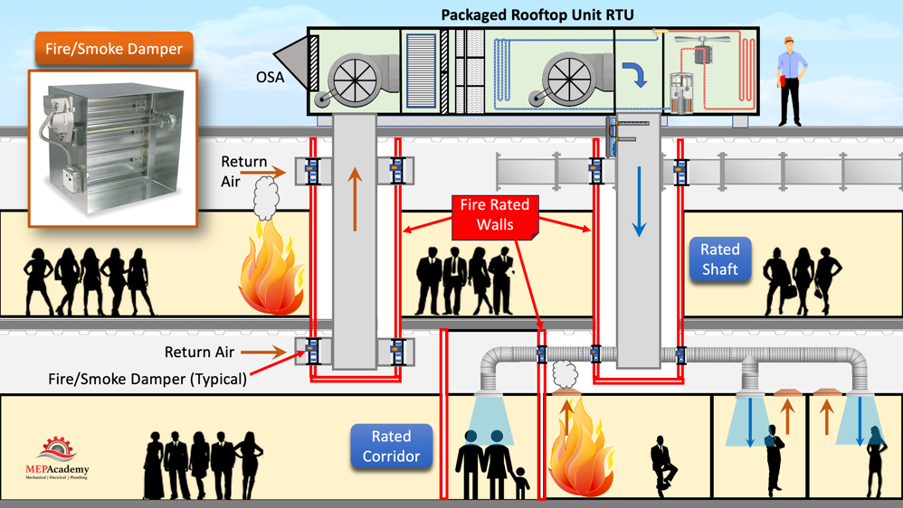
The fan in the air conditioner creates a positive pressure on the supply side pushing the air through the duct, while the return side creates a negative pressure and pulls the air back to the AC unit. You will often find fire rated walls running the length of the corridors which is the life safety pathway for occupants existing the building during a fire. In this case we show a slab-to-slab protective fire barrier with a non-rated ceiling. The fire rated wall is to prevent fire from entering the corridor, so making holes in the wall would defeat the purpose.
To air condition the corridor we’ll install a supply air duct that penetrates the fire rated wall, and we’ll also provide a return grill in the ceiling with an opening in the fire rated wall to allow the return air to make its way back to the air conditioner. Of course, the supply and return won’t be next to each other as shown here, but this is for simplicity of the example.
If we don’t protect the openings, we made in the walls for our air conditioning ducts then smoke and fire could enter the emergency exit corridor, compromising the safe exit of the occupants. Since the return air is under negative pressure, the smoke could be sucked back into the air conditioner and sent back down the supply duct to all the spaces. This would be compromising the safety of all the occupants.
Fire Dampers
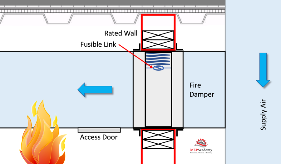
Since we have penetrated the fire rated wall, we’ll need to maintain the fire rating by installing a rated fire damper at the supply and return air wall penetrations. Here is the definition of a Fire Damper according to the NFPA (National Fire Protection Association).
“A fire damper is designed to, and required to, close automatically upon detection of heat (such as a fusible link or heat detector) and to interrupt airflow and to restrict the passage of flame.”
Static and Dynamic Style Fire Dampers
Fire dampers are classified for use in a Static System, (a static system is an HVAC system designed to stop the movement of air within the system at the indication of a fire). Then there is a Dynamic Systems (A dynamic systems is an HVAC system designed to maintain the movement of air within the system at the indication of a fire). So, in a static system the fan should be off, while in a dynamic system the fan will be running as part of an engineered smoke control system.
A fire damper works to protect the opening when the fusible link that holds the damper in the open position, melts. As the fire and heat builds up on one side of the wall, the fusible link reaches the melting point and releases the damper to fall and close off the opening in the duct or wall, preventing the fire from spreading to the other side.
Remember with a static style fire damper the HVAC system fan will be off, while with a dynamic style fire damper the fan will be running because it’s part of an engineered system to control pressure relationships between areas to move smoke out of the building or a protected zone. Dynamic fire dampers are designed to handle the pressure related to a fan operating.
Smoke Dampers
Smoke is an important aspect of any fire, as most people that died in the MGM Grand fire in Las Vegas, died related to smoke inhalation.
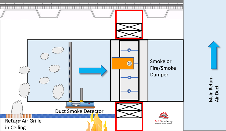
The primary function of Smoke dampers according to the NFPA is to control the movement of smoke in dynamic air distribution systems, and they reduce the possibility of smoke transfer within ductwork or through wall openings. Smoke dampers are installed in corridor and shaft walls, and other barriers engineered to prevent the spread of smoke.
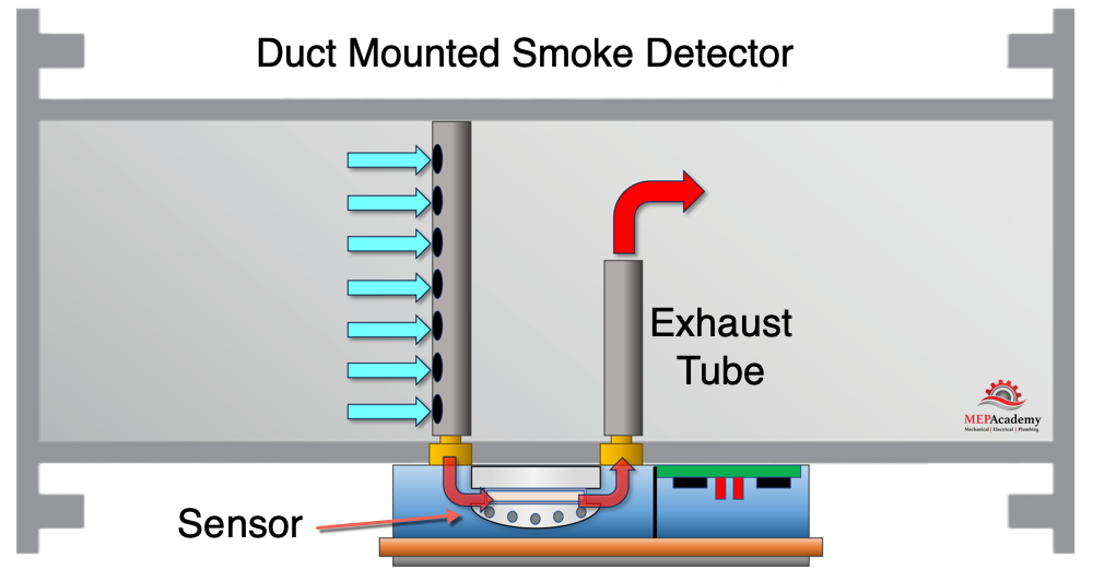
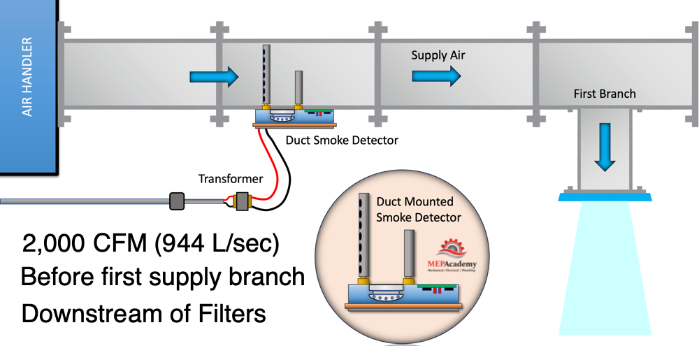
The smoke damper is designed to operate automatically to stop the spread of smoke throughout the air ducts. This is done with the use of smoke detectors that can be located within the duct or with the use of area detectors in smoke compartments.
Combination Fire/Smoke Dampers
There are also fire/smoke damper combinations that protect the opening using both techniques. According to the NFPA, a combination fire/smoke damper is used when a barrier is both rated for fire resistance as well as designed to restrict the transfer of smoke and will meet both the fire damper and smoke damper requirements.
Construction Trades Involved
The construction trades involved in the installation and maintenance of smoke/fire dampers and their scope of work include:
Mechanical Engineers
Mechanical engineers design the HVAC systems and smoke/fire damper layouts. They specify the types of dampers required and their locations to comply with fire safety codes and standards.
HVAC Contractors
HVAC contractors are responsible for installing the ductwork and integrating smoke/fire dampers into the duct systems. Their scope includes the physical installation of the dampers, the wiring required for damper operation, and commissioning of the system.
Electrical Contractors
Electrical contractors are involved in the electrical wiring required for smoke/fire damper activation. This may include wiring for fire alarm panels, smoke detectors, and damper actuators.
Fire Alarm and Life Safety Contractors
These specialists install and maintain fire alarm systems, including the components that detect smoke or fire and the control panels that trigger damper activation.
General Contractors and Subcontractors
General contractors oversee the coordination of all trades involved in the construction project. They ensure that the work of HVAC, electrical, and fire safety contractors is properly integrated into the building’s overall construction.
Building Inspectors
Building inspectors review and approve the installation of smoke/fire dampers to ensure compliance with local building codes and safety standards.
The installation and maintenance of smoke/fire dampers are crucial for the safety of occupants in commercial buildings, especially in the event of a fire. It’s essential that these systems are designed and installed correctly and undergo regular maintenance and testing to ensure they function as intended.