The Microplastic Epidemic. How your daily habits are putting you at risk and what you can do about it. Recent studies have sounded the alarm on a growing health concern: microplastics in our bodies. These tiny plastic particles, less than 5 millimeters in size, have been found in human organs, including our brains, raising serious questions about their long-term impact on our health.
If you prefer to watch the video version of this article, scroll to the bottom.
The Pervasive Nature of Microplastics
Microplastics are everywhere. They’ve been discovered in the clouds atop mountains, in human reproductive organs, and even in infants’ diapers. A shocking study published in Nature Medicine revealed that microplastics are present not only in the brains of deceased individuals but also in their livers, kidneys, and other organs.
Plastic Bottles: A Major Culprit
One of the primary sources of microplastic exposure is plastic water bottles. A recent study found that a liter of bottled water contains an average of 240,000 microscopic plastic particles. Even more alarming, the act of twisting a bottle cap on and off can generate about 500 microplastic particles each time.
Bioaccumulation of Microplastic in our Bodies
Health Risks of Microplastic Accumulation
While the full extent of health risks is still being studied, researchers have identified several potential concerns:
Oxidative stress
Inflammation
Immune dysfunction
Altered metabolism
Impaired cell growth
Abnormal organ development
Potential carcinogenic effects
The Solution: Filtered Tap Water and Stainless Steel Containers
To reduce your exposure to microplastics, consider making these changes:
Switch to filtered tap water: High-quality water filtration systems can remove more contaminants than bottled water, including microplastics
Use stainless steel water containers: Stainless steel offers numerous advantages over plastic:
Switching to filtered water offers numerous health benefits:
Improved taste and odor, Increased hydration due to better taste, Reduced exposure to contaminants, Strengthened immune system, Improved kidney function, Healthier cooking and baking
By making the switch to filtered tap water and stainless-steel containers, you’re not only protecting your health but also contributing to a cleaner environment.
Act today to reduce your microplastic exposure. Invest in a high-quality water filter for your faucet and durable stainless steel water bottles or jugs. Your body—and the planet—will thank you.
Are You Drink Plastic? How to Reduce Microplastic Exposure.
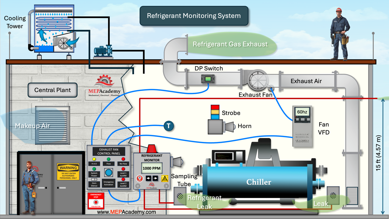
Chillers are used to cool buildings by circulating chilled water through a system that absorbs heat and removes it from the space. They rely on refrigerants to facilitate the cooling process, but if these refrigerants leak into the chiller room, they can pose serious health and safety risks due to potential toxicity or displacement of oxygen. To mitigate this hazard, refrigerant monitors are installed to detect leaks early, ensuring a safe environment for personnel and preventing dangerous exposure.
Refrigerant Monitoring System for Refrigerant Leaks in a Chiller Room
The refrigerant monitor has refrigerant sensors which should be positioned near potential leak points such as chiller units, refrigerant piping joints, and valve stations. Since different refrigerants have varying densities, sensor height plays an important role. Heavier-than-air refrigerants, such as R-123, necessitate sensor installation closer to the floor, typically between 12 to 18 inches above ground level.
Sample tubing used in refrigerant monitoring systems must be carefully installed to prevent contamination and ensure longevity. Exhaust tubing must be routed to a well-ventilated outdoor area to prevent refrigerant buildup within the facility. The length of these tubing runs should be minimized to ensure faster response times and more accurate leak detection results.
Next the chiller room will need an exhaust fan to be activated during a refrigerant leak. The chiller room exhaust fan plays a crucial role in maintaining proper ventilation and air quality. In larger chiller rooms, it typically operates between two speeds with the use of a VFD.
Ventilation System
Refrigeration machinery rooms must have dedicated mechanical exhaust systems to ensure proper ventilation and safety. These exhaust systems are essential for removing potentially hazardous refrigerant leaks, maintaining air quality, and preventing dangerous temperature buildup inside the room.
Minimum Ventilation Requirements
When the machinery room is occupied, the ventilation system should operate at minimum speed or at a rate of at least 0.5 cubic feet per minute (CFM) per square foot of room area (2.54 Liters per square meters) or 20 CFM (9.4 liters per second) per person present, whichever is greater. This ensures that fresh air circulates adequately, preventing the accumulation of refrigerants or other harmful gases. The requirement helps maintain safe breathing conditions for personnel working in the room.
Temperature Control Considerations
The exhaust system must also function to regulate the room’s temperature, preventing excessive heat buildup from equipment operation. Specifically, the fan should run at full speed if the temperature in the room exceeds the setpoint in order to maintain temperature conditions inside that does not exceed:
18-degree Fahrenheit (10 degree Celsius) above the temperature of the incoming air, or
A maximum room temperature of 122-degrees Fahrenheit (50 degrees Celsius), whichever is higher.
Another code states the ventilation or mechanical cooling systems shall provide a temperature of not more than 104 degrees Fahrenheit (40 degrees Celsius) in the chillers mechanical room under design load and weather conditions.
This requirement ensures that mechanical equipment does not overheat, reducing the risk of system failures, fire hazards, or unsafe working conditions for technicians. By maintaining proper airflow and temperature control, the ventilation system improves equipment efficiency, extends system lifespan, and enhances worker safety. Check the local code for the specific requirements for the location of your building.
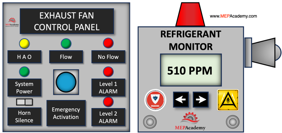
Ventilation Panel and Refrigerant Monitor
Refrigerant Alarm
For our example let’s say that the first level of alarms is set to activate if the refrigerant level exceeds 500 parts per million. This will send a message to the fan to run at full speed, pulling air in through the exhaust air grille located 12 inches (30 centimeters) off the floor. A digital signal can be sent to the strobe light to activate the amber color for a warning. The technician can then search for a leak. Different refrigerants will have different alarm levels, such as R123 may have level one alarm set at 25 parts per million and level two alarm set at 50 parts per million,
The second set of alarms will be activated if the refrigerant continues to increase and reaches 1,000 parts per million at which point the strobe light will start flashing and the horn will sound. Also, at the second level of alarms a signal can be sent to shut down all equipment related to the refrigeration equipment such as compressors and chillers with their pumps.
The mechanical room personnel should immediately exit the chiller room. ASHRAE standard 15 section 8.11.5 has the required calculation for the volume of exhaust air that needs to be provided during an emergency purge based on the mass of refrigerant in the largest system.
The exhaust fan runs at full speed whenever the room temperature exceeds setpoint, the emergency break-glass switch is activated, and if a level one or level two alarm is reached.
Flow and No-Flow Indicators
A Differential Pressure Sensor sends a signal to the ventilation panel indicating one of two condition, flow or No-Flow.
Makeup Air
When exhausting air, it’s important that the fan isn’t starved for air by providing a makeup air louver to bring in fresh air as the fan is running. The louver should be located to provide optimum air movement through the chiller room to the exhaust inlet to remove any leaked refrigerant.
The refrigerant monitor sends a signal to the Ventilation Fan Controller indicating the need for the fan to speed up because of the detection of a minimum level of refrigerant. The controller sends an analog signal to the fans VFD to increase the fans speed as programmed. There will also be a digital signal for starting and stopping the fan. If the refrigerant leak reaches level 2 values in the space the refrigerant monitor sends a digital signal to activate the audio and visual alarms inside the chiller room and outside at the entrance to the room per ASHRAE 8.11.2.1
Break-glass On-Only Control Switch
The exhaust fan requires a break-glass on-only control switch located immediately outside the chiller room door to ensure emergency ventilation in the event of a refrigerant leak. This setup allows personnel to quickly activate the exhaust system without entering a potentially hazardous environment. Since many refrigerants are heavier than air and can displace oxygen, an uncontrolled leak inside the chiller room can create a life-threatening situation. The on-only function ensures that the fan remains running until the area is confirmed safe, preventing accidental deactivation. This safety measure is critical for protecting workers, preventing refrigerant buildup, and complying with ventilation codes in mechanical rooms.
Emergency Off-Only Control Switch Requirements for Chiller Rooms
To ensure safety in refrigeration machinery or chiller rooms, an emergency off-only control switch must be installed immediately outside the primary exit of the room. This switch must be of a break-glass type or have a protective cover, preventing accidental activation while ensuring quick access in an emergency. This requirement applies regardless of the refrigerant type or electrical system used in the installation.
The primary function of this emergency switch is to shut off critical refrigeration equipment inside the machinery room and activate audio and visual alarms. This includes:
Refrigerant compressors, which circulate refrigerant through the system.
Refrigerant pumps, which help move liquid refrigerant within the system.
Normally closed automatic refrigerant valves, which control the flow of refrigerant.
By shutting down these components, the switch helps prevent continued refrigerant leakage or system overpressure, reducing potential hazards.
Additionally, the emergency control system is designed to automatically shut off refrigeration equipment if the concentration of refrigerant vapor in the room exceeds safe limits. Specifically, the system will activate when the vapor detector reads a level that is:
Above the detector’s upper detection limit, or
At 25% of the refrigerant’s lower flammability limit (LFL), whichever is lower.
This automatic shutdown feature is crucial in preventing toxic exposure, oxygen displacement, or fire risks, ensuring a safe environment for personnel and protecting the facility from potential refrigerant-related hazards.
These are the basic components of a refrigerant monitoring system. There are many variations on this layout and the requirements can vary by the code authority where the property is located.
The construction and service industries are on the cusp of a revolution with the increasing adoption of drone technology. Drones—both piloted and un-piloted—are being developed to streamline job site operations, deliver parts and tools, and assist technicians with inspections and repairs. The future promises a more efficient, cost-effective, and safer approach to maintenance and service repairs, reducing costly delays caused by traffic congestion, supply house runs, and labor inefficiencies.
While the potential is immense, significant hurdles must be overcome, particularly in terms of regulatory challenges, safety concerns, and technological advancements. This article explores the current state of drone technology, emerging developments, and the challenges to full-scale implementation in construction and MEP service industries.
Construction Drones for Logistics and Parts Delivery
Current Use of Drones in Construction and Repairs
Drones are already widely used in the construction industry for:
Site Surveys and Inspections: Mapping out job sites, assessing terrain, and conducting aerial inspections.
Progress Monitoring: Providing real-time updates on project status.
Safety Assessments: Identifying hazards before workers enter a site.
Building and Roof Inspections: Assessing HVAC, electrical, and plumbing infrastructure without requiring manual access.
However, as technology advances, drones are poised to take on more active roles in construction and repair services, including part delivery and even direct repair assistance.
Future Applications: Drones for Service Technicians and Repairs
1. Drone-Assisted Parts and Tool Delivery
One of the most practical applications of drones in construction and repair work is delivering small parts and tools to technicians on rooftops or job sites. Currently, technicians frequently waste time battling traffic to pick up replacement parts or tools, causing delays that cost businesses money.
With piloted or autonomous drones, companies could deploy drones from local supply warehouses or service hubs, delivering HVAC, electrical, or plumbing components directly to job sites in minutes. This approach could eliminate hours of wasted travel time and significantly improve efficiency.
The Future of Drones in Construction
Technology Making This Possible
Current:
DJI’s FlyCart 30 is an early-stage drone capable of carrying payloads up to 66 lbs (30 kg) over distances of up to 16 miles.
Zipline’s fixed-wing drones are used in medical supply delivery, showcasing a model that could work for construction.
In Development:
Automated storage hubs with drone dispatch systems, reducing human involvement in retrieving and loading parts.
Improved battery and hybrid power systems to increase drone flight ranges and payload capacities.
AI-based navigation and object recognition to allow drones to deliver parts precisely to a technician’s location.
2. Drone-Assisted Repairs and Inspections
Drones could eventually become more than just delivery vehicles. They could perform minor repairs and assessments autonomously or remotely with the assistance of a human operator.
Thermal imaging and infrared cameras to detect electrical faults, HVAC inefficiencies, or plumbing leaks.
Robotic arms and manipulators for minor repairs, such as tightening bolts or securing electrical connections.
Augmented reality (AR) and AI integration, where drones assist technicians with visual overlays and diagnostic tools.
Drones for Assistance in Repairs and Parts Delivery
3. AI and Swarm Technology for Construction Assistance
Future drones may not operate alone but rather in coordinated swarms to perform complex tasks.
Swarm drones could work together for inspections, collectively scanning a building’s systems faster than a single drone.
AI-driven construction drones could assist in moving materials around a job site, reducing reliance on traditional equipment. Checkout these Drones.
Challenges to Drone Integration in Construction and Service Industries
While the potential for drones in construction and repair services is high, there are significant regulatory, safety, and technical challenges that must be addressed before widespread adoption.
1. Regulatory Hurdles
The FAA (Federal Aviation Administration) and other global aviation authorities have strict rules on drone usage, particularly for commercial purposes.
Weight and altitude restrictions limit the types of parts that can be transported.
Airspace control issues make it difficult to deploy drones in urban environments without interference.
Possible Solutions:
FAA-approved Beyond Visual Line of Sight (BVLOS) technology will be crucial for expanding drone applications.
Development of dedicated drone corridors and integrated air traffic control systems.
2. Safety and Liability Concerns
Collision Avoidance: Drones flying near construction sites, urban buildings, and technicians pose risks of accidents.
Payload Security: Parts and tools must be safely secured to avoid drops that could injure workers or pedestrians.
Cybersecurity: Drones must be hacker-resistant to prevent unauthorized control or data breaches.
3. Battery and Payload Limitations
Current battery technology limits flight time and range.
Heavy equipment requires stronger motors and larger drones, which might be impractical for job sites.
Ongoing research in hydrogen fuel cells and advanced battery tech may solve these issues.
The Road Ahead: When Will Drone Integration Become Mainstream?
The integration of drones in construction and service industries will likely happen in phases:
Short-Term (2025-2028): Increased use of drones for inspections, mapping, and surveillance with improved AI analytics.
Mid-Term (2028-2035):Routine delivery of small parts and tools to technicians using autonomous drones, with regulatory advancements allowing BVLOS flights.
Long-Term (2035 and Beyond): Full integration of automated repair drones, robotic maintenance systems, and AI-controlled site operations.
Conclusion
The future of piloted and autonomous drones in construction and repair services is promising, with the potential to significantly reduce delays, improve technician efficiency, and cut costs. While regulatory and technological challenges remain, advancements in AI, battery technology, and automated flight control will gradually pave the way for widespread adoption.
As these innovations develop, companies in the construction and MEP industries should stay informed and explore ways to integrate drone technology into their workflows—because the future of work may soon take flight. Leave your ideas in the comments below. Do you use drones now, or do you see yourself using them in the future?
If you found this video helpful, be sure to check out our HVAC and Plumbing Estimating Spreadsheets to streamline your construction bidding process, checkout our HVAC, Electrical and Plumbing Construction Forms to help you run your business and explore our Online Courses for in-depth training. You’ll find everything you need to level up your skills and efficiency. Links are in the description below.
If you like that video, please give it a thumbs up and subscribe to our channel, thank you.
Water source heat pumps are versatile and energy-efficient HVAC systems widely used in commercial and institutional buildings, such as office spaces, schools, and healthcare facilities. These systems utilize a centralized water loop to transfer heat between individual heat pumps, making them ideal for buildings with diverse thermal demands across different zones.
If you prefer to watch the video of this presentation, then scroll to the bottom.
How Water Source Heat Pumps Work
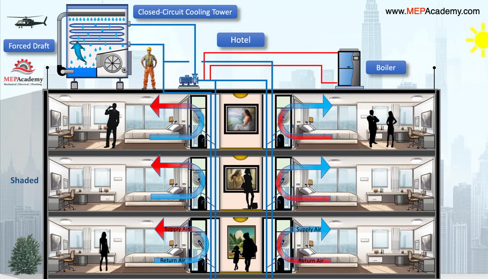
Water source heat pumps use the refrigerant cycle to either absorb or reject heat. Each unit connects to a water loop that serves as a medium for heat exchange. During cooling, the heat pump transfers heat from the indoor space to the water loop. Conversely, during heating, the heat pump extracts heat from the loop and delivers it to the indoor space. Each zone has its own water source heat pump, and they’re all connected to the same water loop.
Fluid Cooler serving Water Source Heat Pumps in a Hotel
Interaction Between the Fluid Cooler and Boiler
The water loop in a Water source heat pump system requires temperature regulation to ensure efficient operation. Two key components that facilitate this are the fluid cooler and the boiler:
Fluid Cooler
During peak cooling conditions, the water loop temperature rises due to heat rejection from various zones. The fluid cooler dissipates this excess heat to the outside air, maintaining the water loop within the desired temperature range.
Boiler
During heating seasons or when the water loop cools down excessively, the boiler adds heat to the loop, ensuring it remains warm enough to support heating operations across zones.
Typical Water Loop Temperatures
The water loop in a Water source heat pump system is typically maintained between 70 degrees Fahrenheit and 90 degrees Fahrenheit (21C to 32C). This range ensures efficient operation for both heating and cooling modes, balancing the energy requirements of all zones while optimizing the performance of the heat pumps.
Heat Contribution and Removal in Different Building Zones
In a Water source heat pump system, different zones can either add or remove heat from the water loop based on their heating or cooling needs:
Heat Addition: Zones requiring cooling transfer heat into the loop, raising the loop temperature.
Heat Removal: Zones requiring heating extract heat from the loop, lowering the loop temperature.
This dynamic exchange creates an efficient, self-balancing system where zones in cooling mode can offset the energy needs of zones in heating mode, reducing the overall demand on the fluid cooler and boiler.
Open vs. Closed Loop Systems
Water source heat pump systems can operate with either an open loop or a closed loop configuration:
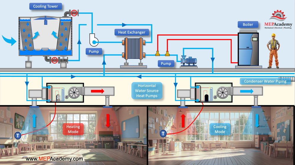
Water Source Heat Pump System with Open Cooling Tower and Heat Exchanger
Open Loop
In this setup, water is drawn from a natural source, such as a lake, river, or well, and is cycled through the system. After the heat exchange, the water is discharged back into the source. Open loops are highly efficient but may require permits and careful water quality management.
Closed Loop
Here, the water circulates within a sealed piping system, transferring heat to or from the fluid cooler or boiler. Closed loops are easier to maintain and protect against contamination but may involve higher upfront costs for piping and installation. Additionally, closed loop systems protect the heat exchangers of the water source heat pumps from contamination, enhancing their longevity and performance.
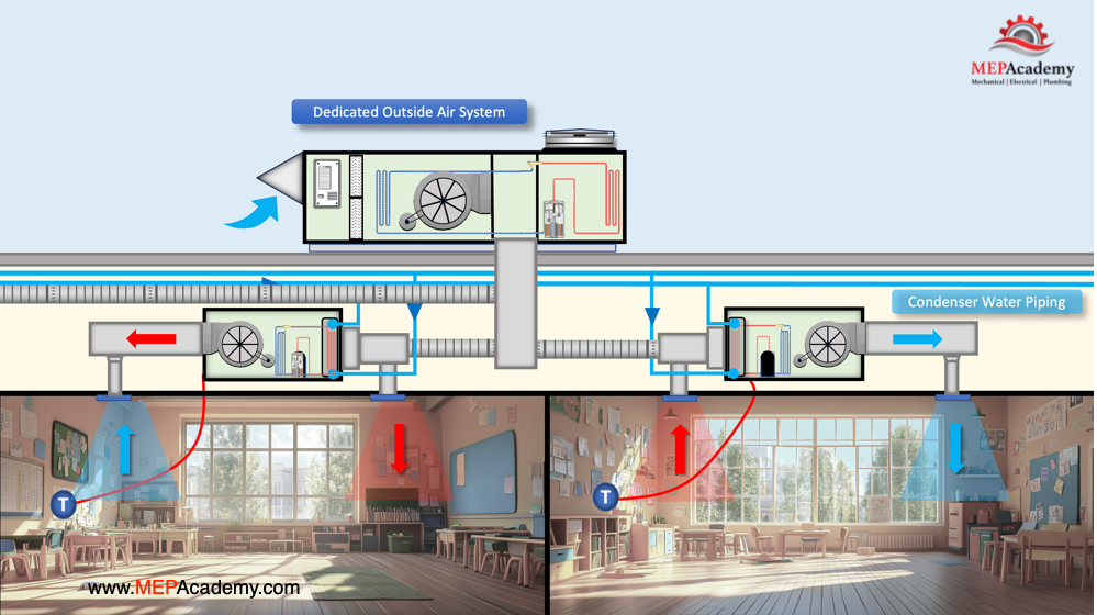
The Role of a Dedicated Outside Air System (DOAS)
To comply with building codes and provide fresh air, many Water source heat pump systems incorporate a Dedicated Outside Air System. This unit provides ventilation air that is conditioned independently of the Water source heat pumps, improving indoor air quality and ensuring compliance with ASHRAE standards.
Dedicated Outside Air System DOAS serving a Water Source Heat Pump System
A Dedicated Outside Air System may:
Pre-condition incoming air by heating, cooling, or dehumidifying it before distribution.
Work in tandem with Water source heat pumps to manage latent and sensible loads more effectively.
A Plate and Frame Heat Exchanger is a critical component in Water Source Heat Pump systems when utilizing an open-source cooling tower. It is installed between the open-loop (cooling tower) and the closed-loop (water source heat pumps), effectively creating two separate water loops.
Function of the Plate and Frame Heat Exchanger
Separation of Water Loops:
The open loop consists of water circulating between the cooling tower and the plate and frame heat exchanger. This water is exposed to the atmosphere, making it susceptible to dirt, debris, and biological growth.
The closed loop contains clean, treated water circulating between the plate and frame heat exchanger and the water source heat pumps inside the building.
Protection of Water Source Heat Pumps:
Cooling towers are prone to biological growth, scaling, and debris accumulation. If this contaminated water were to circulate directly through the water source heat pumps, it could foul or clog their internal heat exchangers.
By using a plate and frame heat exchanger, the open loop contaminants are isolated from the water source heat pumps, reducing maintenance and extending equipment life.
Heat Transfer Process:
The heat exchanger transfers heat between the open and closed loops without mixing the water.
When in cooling mode, heat from the closed-loop water is rejected through the heat exchanger into the open loop, which then carries it to the cooling tower for dissipation.
In heating mode, heat is absorbed from the closed-loop water and transferred to the water source heat pumps for space heating. If the loop water is too cold then the boiler is activated to bring the minimum water temperature up to set point.
Cost vs. Benefit
Added Cost: Installing a plate and frame heat exchanger introduces additional upfront costs, including the cost of the heat exchanger itself, piping modifications, and additional pumps.
Reduced Maintenance & Increased System Longevity: The cost is justified by the long-term benefits, as it:
Prevents fouling of the heat exchangers inside the water source heat pumps.
Reduces chemical treatment needs for the closed-loop water.
Lowers maintenance costs by preventing scaling, biological growth, and corrosion in the closed-loop system.
While adding a plate and frame heat exchanger increases the initial investment, it significantly enhances system reliability, efficiency, and lifespan by keeping the closed-loop water clean and free from contaminants. This setup is a best practice when using open cooling towers with water source heat pump systems to prevent fouling and ensure optimal long-term performance.
Basic Controls for the Fluid Cooler and Boiler
Effective operation of the fluid cooler and boiler relies on an integrated control strategy that maintains optimal water loop temperatures. Key controls include:
Temperature Sensors: Measure water loop temperatures to determine when to activate the fluid cooler or boiler.
Set Point Controllers: Maintain the water loop temperature within the desired range (e.g., 70 degrees Fahrenheit to 90 degrees Fahrenheit)(21C to 32C). The set point temperature can vary based on building load, outdoor conditions, and efficiency goals. A greater temperature difference in the loop improves overall system energy efficiency but reduces efficiency at the individual zone level heat pumps. If you widen the Delta T from 60 to 90 degrees Fahrenheit (15.5C to 32C), that gives the system level a 30-degree temperature difference, meaning the boiler will run less often, but the water source heat pumps requiring heating may run less efficiently due to the cooler water temperature.
Staging Controls: Enable or disable stages of the fluid cooler or boiler based on real-time demand.
Seasonal Mode Switching: Automatically switch between heating and cooling priority based on outdoor temperatures or building load profiles.
Water source heat pumps provide an efficient and flexible solution for modern HVAC needs, especially in buildings with diverse heating and cooling requirements. By leveraging a balanced water loop, supplemented with a fluid cooler and boiler, these systems optimize energy use across different zones. When integrated with a Dedicated Outside Air System and managed by robust control strategies, Water source heat pump systems deliver exceptional performance while meeting energy efficiency and ventilation standards.