How long should you run your air purifier? Air purifiers have become essential in many homes, especially for those dealing with allergies, asthma, pet dander, smoke, or just a general desire for cleaner indoor air. But one common question is: How long should you run your air purifier for it to work effectively?
Let’s break it down.
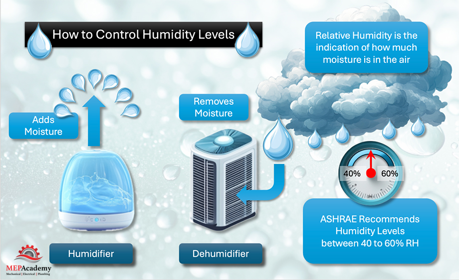
1. Understanding How Air Purifiers Work
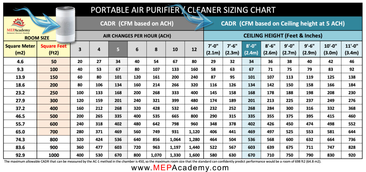
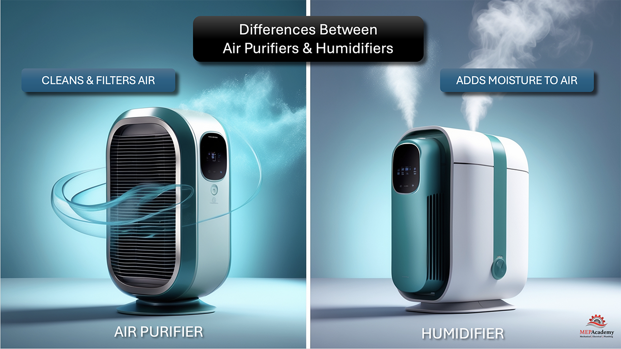
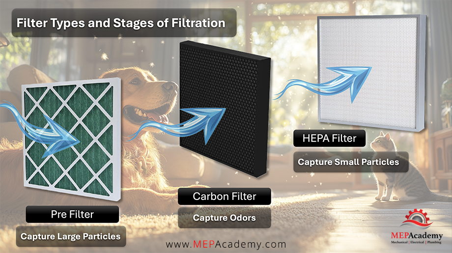
Air purifiers draw in air from the surrounding environment, filter it through various stages (like HEPA filters, activated carbon, UV lights, or ionizers), and then release the cleaned air back into the room. The efficiency of this process depends on the air changes per hour (ACH) and the clean air delivery rate (CADR) — two key performance metrics.
ACH indicates how many times an air purifier can exchange the entire air volume in a room in one hour.
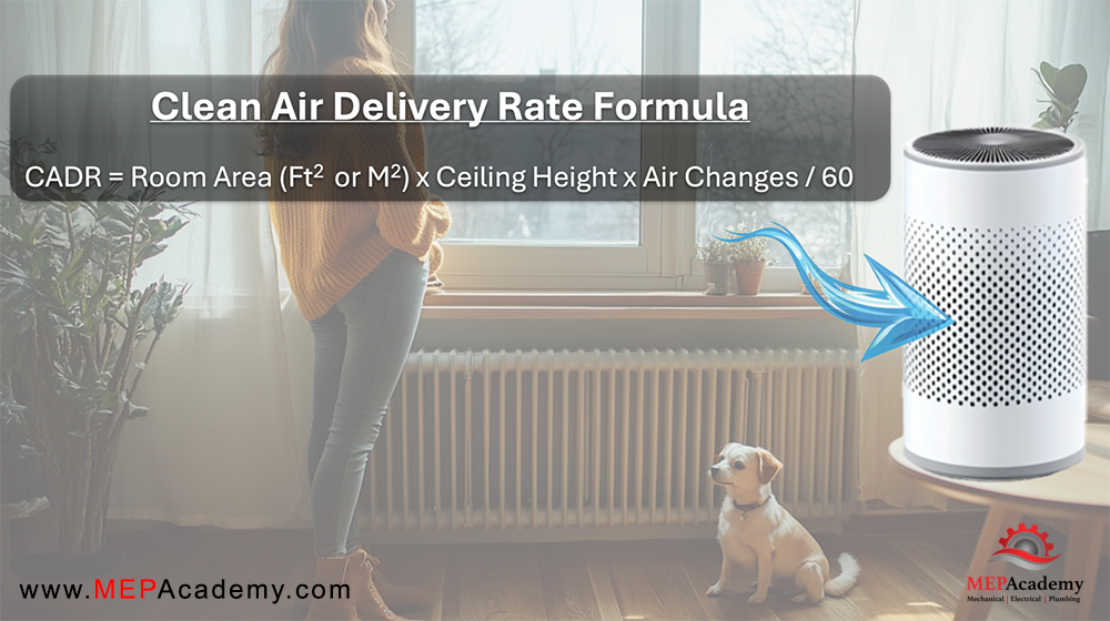
CADR tells you how quickly the purifier can remove specific contaminants like dust, pollen, and smoke.
These determine how fast and effectively your air is cleaned. Checkout current Air Purifier Prices
2. So, How Long Should You Run an Air Purifier?
For Maximum Effectiveness: Run It Continuously
The most effective way to maintain clean indoor air is to run your air purifier continuously, especially if:
- You have allergies or respiratory conditions.
- You live in an area with high pollution or wildfire smoke.
- You have pets that shed dander and fur.
- Someone smokes indoors.
- You cook frequently and want to reduce odors and airborne grease.
Modern air purifiers are designed to run 24/7 and are energy efficient, especially those with Energy Star certification. Most have sensors to adjust fan speed based on air quality levels, helping save power and extend filter life.
Minimum Recommended Time: 12+ Hours a Day
If running it all day isn’t feasible, aim for at least 12 hours per day. Ideally, split the usage across times when you’re at home — especially in the bedroom at night and living areas during the day.
3. How the Air Quality Index (AQI) Affects Run Time
The Air Quality Index (AQI) is a standardized system used to report and track air pollution levels. It’s a helpful tool that can guide how long and how often you run your air purifier — especially if you’re in an area prone to poor outdoor air quality.
What Is the AQI?
The AQI measures five major air pollutants regulated by the Clean Air Act:
- Ground-level ozone
- Particulate matter (PM2.5 and PM10)
- Carbon monoxide
- Sulfur dioxide
- Nitrogen dioxide
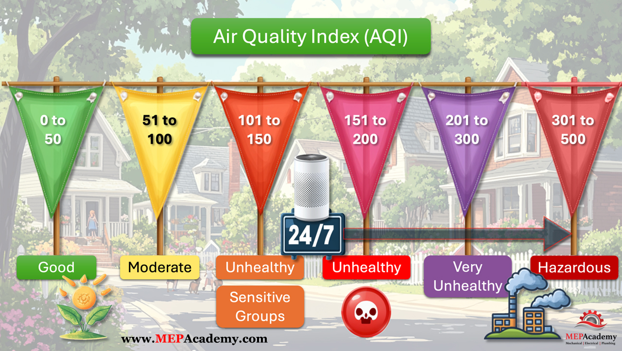
Each pollutant is given a score, and the highest value becomes the AQI for that location. The scale runs from 0 to 500 — the higher the number, the greater the level of pollution and the more serious the health concern. You can check your local AQI using apps like AirVisual, Plume Labs, EPA’s AirNow, or even some smart air purifiers with real-time AQI monitors.
AQI Categories and What They Mean
| AQI Range | Air Quality | What It Means | Suggested Action |
| 0–50 | Good | Air quality is satisfactory | Normal usage |
| 51–100 | Moderate | Acceptable, but could affect sensitive individuals | Run purifier during peak hours |
| 101–150 | Unhealthy for Sensitive Groups | People with asthma or allergies may feel effects | Run purifier more frequently |
| 151–200 | Unhealthy | Everyone may begin to experience effects | Run Purifier 24/7 |
| 201–300 | Very Unhealthy | Health alert: serious effects possible | Stay indoors, run multiple purifiers if needed |
| 301–500 | Hazardous | Emergency conditions | Seal the space and use purifiers at maximum capacity continuously |
How to Adjust Run Time Based on AQI
On good air days, you can reduce run time slightly — though keeping the unit running still helps maintain indoor freshness.
On moderate to unhealthy days, run the purifier in common areas and bedrooms continuously.
During high AQI events like wildfires, dust storms, or pollution spikes, keep windows closed and run the purifier 24/7 on high or auto mode.
4. Other Factors That Affect Run Time
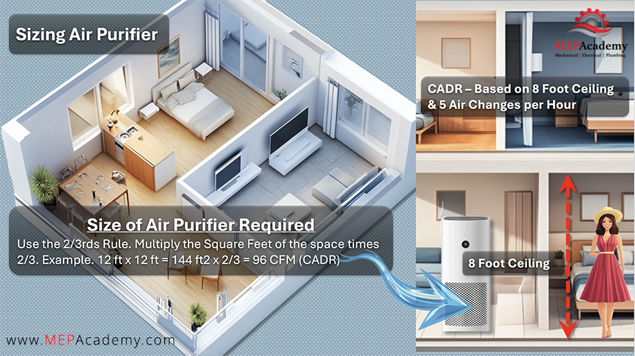
Room size: Larger rooms may take longer to cycle the air. Match the purifier’s CADR to your room’s square footage.
Pollution level: Homes with pets, smokers, or urban settings may need longer operation.
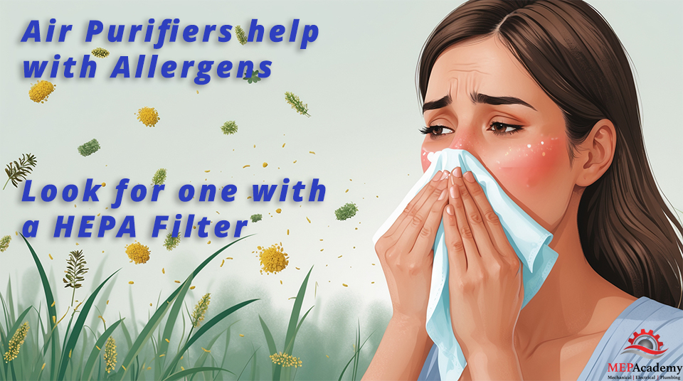
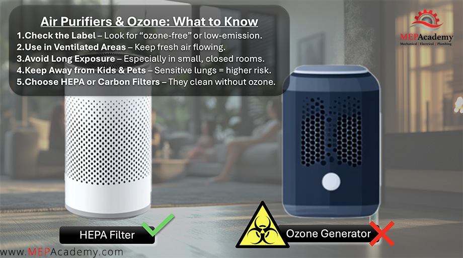
Filter quality and type: HEPA filters are highly efficient and ideal for allergens; carbon filters help with odors and VOCs.
Airflow and layout: Open-plan homes or rooms with poor ventilation may need more coverage or longer run times.
5. Tips for Optimal Use
✅ Keep doors and windows closed while the purifier is running — this prevents new pollutants from entering.
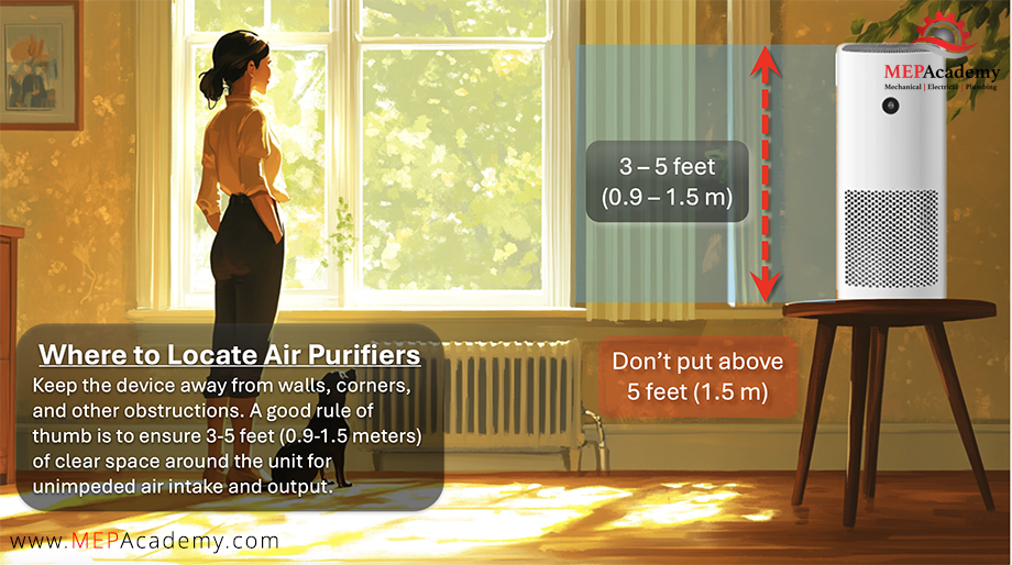
✅ Place it centrally in the room but away from walls and obstructions.
✅ Clean or replace filters regularly based on the manufacturer’s schedule.
✅ Use auto mode or a smart timer to balance performance and energy savings.
✅ Track AQI levels daily and adjust purifier usage accordingly.
6. ✅ Advantages of Running an Air Purifier Continuously (24/7)
| Advantage | Details |
|---|---|
| Consistent Air Quality | Running it all day ensures pollutants like dust, pollen, smoke, and pet dander are continuously filtered out. |
| Ideal for Allergy & Asthma Sufferers | Maintains a low-allergen environment at all times, reducing symptoms. |
| Handles Sudden Air Quality Changes | Helps protect against unexpected spikes in pollutants (e.g., wildfire smoke, cooking odors). |
| Better for Pet Owners & Smokers | Keeps up with constant sources of dander, hair, and tobacco smoke. |
| Smart Features Work Best | Many purifiers with sensors or auto modes optimize performance best when left on. |
| Improves Sleep Quality | Quiet models improve nighttime breathing and comfort, especially for sensitive individuals. |
| Low Energy Use | Most modern units are Energy Star certified and designed to run efficiently long-term. |
7. ⚠️ Disadvantages of Running an Air Purifier Continuously
| Disadvantage | Details |
|---|---|
| Increased Electricity Usage | Though usually minimal, running 24/7 will increase your energy bill slightly, especially with large or multiple units. |
| Filter Replacement Costs | Filters may need to be replaced more frequently if the unit runs non-stop. |
| Noise (for Some Models) | Some purifiers, especially on higher fan speeds, may produce noticeable sound, which could be disruptive in quiet spaces. |
| Possible Over-Drying (Rare) | In some environments, constant air movement can lead to slightly drier air—especially in winter—though this is rare with modern purifiers. |
| Wear and Tear | Continuous use may reduce the unit’s lifespan slightly, depending on build quality and maintenance. |
💡 Tip:
To balance the pros and cons, you can:
- Use auto or eco mode when available.
- Run on low or sleep mode at night.
- Set smart timers to focus on peak pollution times (like during cooking or pollen hours).
- Maintain filters to keep performance high and extend unit life.
8. Conclusion: Let AQI and Conditions Guide You
To keep your indoor air truly clean, run your air purifier continuously or for long stretches daily, especially when AQI is moderate or worse. Think of it like your refrigerator — you wouldn’t turn it off for hours and expect your food to stay fresh. Similarly, purified air doesn’t stay clean for long if the purifier is off.
Monitor your AQI, adjust your run time, and enjoy cleaner, healthier air year-round.
Checkout the current pricing for Air Purifiers
Frequently Asked Questions
1. How many hours a day should you run an air purifier?
For best results, run your air purifier continuously (24/7), especially if you have allergies, pets, or live in an area with high pollution. At a minimum, aim for 12 hours a day to maintain clean air in frequently used rooms.
2. Should I leave my air purifier on all the time?
Yes, most air purifiers are designed for continuous use and are energy-efficient. Leaving it on helps maintain consistently clean indoor air. Many models have auto or eco modes that adjust fan speed based on real-time air quality, helping reduce power consumption.
3. Does outdoor air quality (AQI) affect how long I should run my air purifier?
Absolutely. When the AQI is high (especially above 100), you should run your purifier continuously and keep windows and doors closed. Poor outdoor air quality can rapidly degrade indoor air, making extended purifier use essential.
4. Is it safe to sleep with an air purifier on at night?
Yes, it’s not only safe but highly recommended. Running an air purifier while you sleep helps filter out allergens, dust, and pollutants, improving sleep quality and reducing nighttime allergy symptoms.
5. Can I run an air purifier with windows open?
While it’s possible, it’s not ideal. Open windows allow outdoor pollutants to enter, making it harder for the air purifier to keep up. For maximum efficiency, keep windows and doors closed while the purifier is running.
6. How do I know if my air purifier is working effectively?
Look for signs like cleaner-smelling air, less dust buildup, and fewer allergy symptoms. Smart air purifiers often have real-time air quality monitors. Also, ensure filters are clean and replaced regularly.