6 Steps for Designing HVAC DDC Controls. In this article we’ll cover the six basic steps to designing a DDC controls system. By following these six steps you’ll get a basic understanding of what it takes for a control engineer to design a basic controls system. Then, we’ll explain the various types of points and controllers that are used in our example.
If you prefer to watch the Video of this presentation, then scroll to the bottom or click on this link. “6-Steps for Designing HVAC DDC Controls”
At the heart of a properly operating HVAC system is the layer of controls that keep the system operating as intended. If the controls aren’t functioning properly then there will be a loss of occupant comfort and an increase in energy consumption. The controls must be designed to work with the HVAC system.
Let’s start by making a list of the equipment we’ll need for our HVAC design.
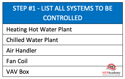
Step #1 List all Systems to be Controlled
First make a list of all the systems that will need to be controlled. This could include the heating hot water plant, chilled water plant, air handlers, fan coils and VAV boxes. For our example we’ll use a Heating Hot Water boiler system. The example we’ll use will be from the perspective of the boiler’s controller.
Step #2 – Make a Schematic Controls Diagram
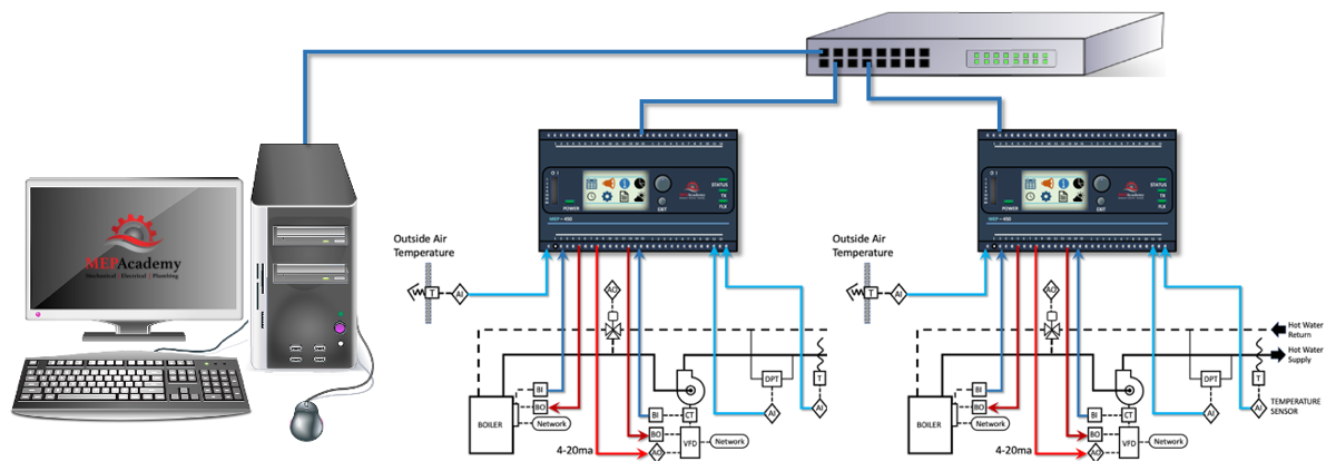
From your list of systems you can make a simple controls diagram. Draw the equipment for your system on a piece of paper or into your computer program. Arrange the equipment starting with the source, such as a boiler or chiller. Then put any pumps, VFD’s, control valves and sensors that might be required.
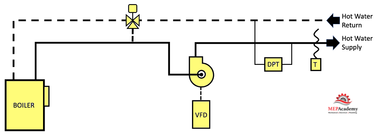
Here we show a boiler, it’s associated heating hot water pump, Variable Frequency Drive (VFD), a 3-way control valve and a Differential pressure transmitter (DPT), and a Heating Hot Water Supply Temperature Sensor. These are the basic components for our system.
Step #3 – Identify Points on the Control Diagram
The sequence of operation will identify points of control that will need some form of connection to a controller.
There are four basic points that are used in DDC control diagrams.
#1 Analog Outputs (AO) – Modulate a damper or valve through a range of flow. The control signal is usually sent as a 0-10 VDC or 4-20 milliamp electrical signal to the device to be controlled. Since this is too small of an electrical signal to operate a damper or a control valve, there will be a transducer that converts the analog signal to a higher electrical power to operate the device. The diagram shows we have an analog output to 3-way control valve and the variable frequency drive.
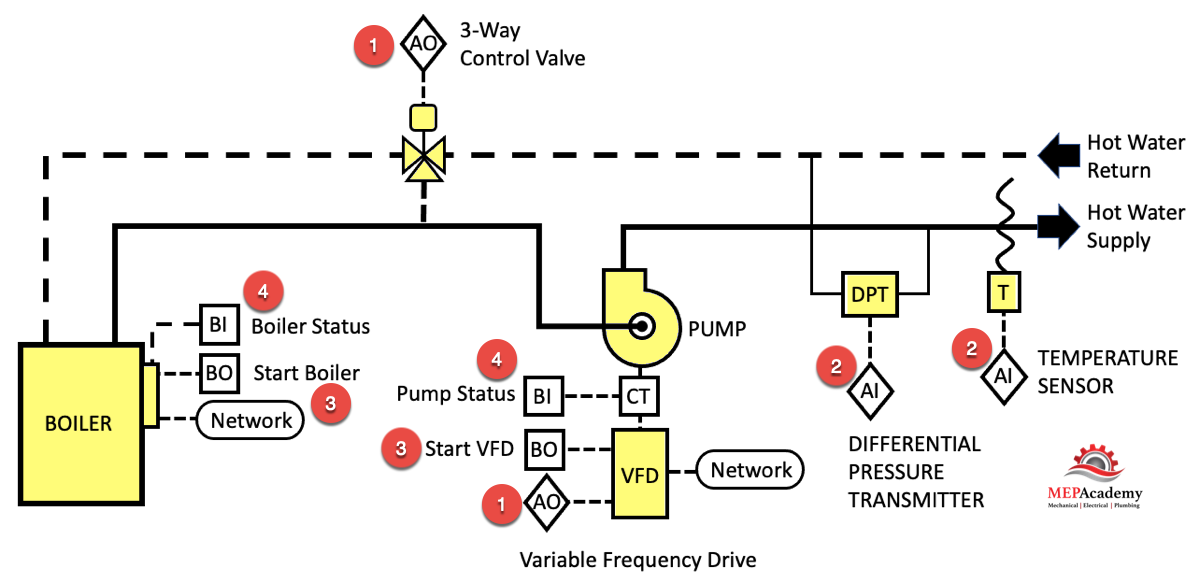
#2 Analog Inputs (AI) – A range of values from Input sensors for items such as temperature, pressure, CO2, and humidity. The analog signal coming from the device will be converted to a digital signal within the controller so it can be processed by the computer. We have two analog inputs in our diagram, a temperature sensor and the differential pressure transmitter.
#3 Binary Outputs (BO) – Often a simple command to enable a piece of equipment to start or for opening a damper or valve. Also known as Digital Outputs (DO). In our diagram we have two binary outputs for starting the boiler and pump.
#4 Binary Inputs (BI) – Used to retrieve the operating status of a piece of equipment. This notifies the controller if a certain piece of equipment is running. Also known as Digital Inputs (DI). The diagram shows two binary inputs for the confirmation that the boiler and pump are running.
Step #4 – List the Sequence & Modes of Operation
Describe what occurs to the system and equipment during occupied and unoccupied modes. Indicate whether a piece of equipment is started or stopped, such as turning on and off a boiler, or whether the item needs to create an alarm for failure.
Using the sequence of operation we’ll expand the modes of operation to include trigger points for the system or piece of equipment. This could be temperatures, pressures, alarms and various differential temperature and pressure ranges. The sequence of operation is a very important part of the controls design as it informs the system operator how the system will operate to achieve the design goals.
This is like the verbal commands you receive when using a GPS guided map in your car. It’s step by step instructions on what needs to be done to achieve the design intent. The setpoints are clearly stated along with how they are determined, while each variable is controlled by a single control loop.
The sequence will define how each device is controlled in the various modes of operation, such as normal operation, occupied or unoccupied mode, shut down mode, and alarm mode if required. Its normal mode of operation should be stated clearly.
Control engineers have saved templates of various sequences of operation that they can use or modify to fit the requirements of any project.
Here is what a sequence of operation might look like for our Heating Hot Water system.
Sequence of Operation for Heating Hot Water System
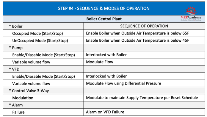
- DDC Controller shall start boiler when Heating Hot Water Pump is verified to be running.
- Hot Water boiler “ON” status to be confirmed, or an alarm is activated.
- As the heating hot water piping pressure differential decreases, pump speed will increase. As the HHW piping differential pressure increases, pump speed will decrease.
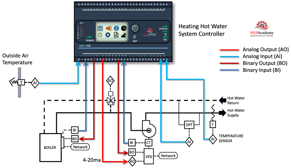
- DDC Controller will modulate the pump speed with a 4-20 milliamp signal to the variable frequency drive based on differential pressure.
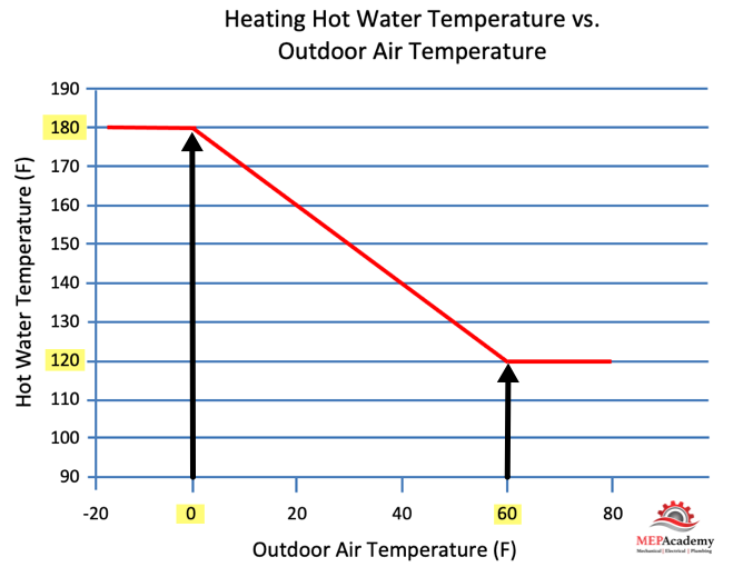
- DDC Controller shall reset heating hot water temperature based on outside air temperature reset schedule (Hot water temperature = 180°F at 0°F outside air temperature, hot water temperature = 120°F at 60°F outside air temperature).
Control Points
- Heating Hot Water Pump Status (Binary Input)
- Boiler Enabled “ON” (Binary Output)
- Boiler Status (Binary Input)
- Boiler Temperature Reset based on Outside Air Temperature (Analog Output)
- Outside Air Temperature (analog Input)
- Heating Hot Water Piping Differential Pressure (Analog Input)
- Variable frequency Drive for Pump (Analog Output)
- Variable Frequency Drive (VFD) Failure (Binary Input)
This of course is a very simple explanation of the sequence of operation. The actual sequence will involve more descriptive details, but this gives you an idea of how they are generated. One item not discussed is scheduling, which includes what happens in occupied and unoccupied modes.
Step #5 – Make a Controls Points List
This is a simple chart that shows all the control points for the equipment and system. Points provide data for use in controlling the environment and can be used in software calculations or computer logic. Points provide the controller with information on the temperature, pressure, carbon monoxide level, humidity, the quantity of air or water flowing in a system, including other data inputs, along with output command signals.
There are points that are considered hardware and provide data to a controller or receive data from the controller, and then there are software points or virtual points that are housed within the control logic. We’ll cover the hardware points for a Heating Hot Water System containing a single boiler.
The first column is a description of the point. The following columns will be the various types of points that maybe required for any of the points described. There are analog and digital inputs and outputs, alarms, and other points. A number value indicates that the point is required. The control point can be an input sensor or the output control for the modulation of a damper or control valve.
Large systems will require a lot of points, while a smaller system will require much less. The more points the more cost associated with furnishing and installing the controls system. The points list gives a quick overview of just how many points are involved with the system.
Each point will need to be hardwired or configured wirelessly into the system or equipment controller. The controller allows various input and output points to be connected.
In a plans and specification project you’ll find the points list and the sequence of operations on the drawings or in the specifications. A clearly written and accurate points list and sequence of operation will provide the installing contractor with a clear roadmap to achieve the engineer’s requirements.
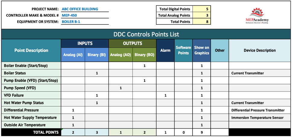
Let’s look at the first two columns which are the inputs.
Looking at our example we see a binary output signal to enable or turn on the boiler. Next we see a binary input using a current transmitter to see if the power is flowing to the boiler. Next we have a binary output signal to turn on the pump through the VFD, while there is a analog output to control the speed of the pump using a differential pressure sensor. Once again we use a current transmitter to confirm that a piece of equipment is running, in this case the pump.
Supply water temperature sensor which requires an analog input from the sensor to the controller. There is an analog input for the differential pressure sensor which gives an indication of the pressure difference between the supply and return water piping. This will help control the VFD speed. If the pressure increases in the system, then the VFD will slow down the pump motor.
Also, on the list of points we see the boiler status requirement which involves a digital input. This can be done with a simple current transmitter that is connected to the boiler which shows current flow when in operation.
Remember that analog points provide for a range of measurements or control variability, while a digital point is two states, either on/off, start/stop or similar.
A digital input device could be a flow switch that will indicate whether the fan is blowing air or is off. It could also be a current device that detects the flow of electricity, which would then make a contact to indicate that the motor is running. Another device is the pressure sensor which is a digital input point that informs the controller that there is pressure in the system caused by the fan blowing air. All these devices are examples of digital input points for the purpose of obtaining the status of a piece of equipment.
Next, we’ll look at the two columns of outputs. Analog outputs would direct devices to modulate like that of a control valve or damper, while digital output devices could start or stop a piece of equipment.
A digital output signal is sent to the VFD enabling the pump motor to run, while the analog output signal to the VFD will adjust its speed. The points list also shows that we want a digital output to operate the turning on and off the boiler.
There is a column for alarms that need to be generated to alert the facility staff of a problem or for alarm tracking. There is a column to indicate if the item described needs to be added to the front-end graphical display. The column identified as Software points can be used for in-direct points that transmit data on the network for use by other controllers. This allows sharing of any analog, digital or logic accumulated on this system.
There is an extra column for other devices or points that are not tied into the controller but may need to be considered to have a functional system. These could include safety devices, like high-limit switches that protect the system but are not part of the input or output of the controller. Some valves or dampers don’t require a controller to operate as they can just require an on/off position which can be done with a thermostat or safety limit switch.
The points list could indicate the total amount of points that are currently designed into the system, but you’ll find that most engineering firms don’t show this on their drawings. This is something that they use behind the scenes to keep track of how many inputs and output ports have been assigned on the controller. The controller has a limited number of inputs and outputs, so it’s important to know how many have been used, and how many remain. The engineer may specify that there are to be so many spare spots on the controller for future expansion.
Step #6 – Write Controls Specifications
Another step after the fifth, would be the design of the overall system architecture and for the controls engineer to write the controls specification, but that is beyond the scope of this article.
Looking at our points list for our boiler system controller we can see all the input and output devices that need to be connected to the controller.
Controllers
Controllers can be provided with the equipment or added on by the control’s contractor. This takes coordination between the installing HVAC contractor who is responsible for buying the major HVAC equipment and the controls contractor. They can be the same company if the HVAC contractor has their own controls division.
Controllers are like small computers that can be made specifically for a piece of equipment or system function. They are designed in all sizes with varying numbers of inputs and outputs. Small systems require a small number of inputs and outputs, while large system can be comprised of many inputs and outputs along with sub-networks of other controllers. The controller requires input signals in order to make decisions on output signals. For hazardous areas where an explosion could occur from a digital controller, there are pneumatic controllers that can be used, or with some additional money the electronic ones can be made explosion proof.
Controllers have various analog and digital input and output connections that allow for the normal points required for that piece of equipment. There are also universal controllers that allow any connection to accept either analog or digital points of connection. The controllers will be located throughout the facility to operate the various pieces of equipment and systems. The controllers will be connected with communication cable into a network that provides the facility operator with an overview of the total system.
These controllers are configurable to allow programmers to set parameters that match the design requirements. The code can be customized for various setpoints (temperature, carbon monoxide levels, pressure, humidity), time schedules, alarms, trending, timers, and logic.
The points list will identify all the input and outputs for each of the controllers. Each controller has its own input and output devices, specifically designed for the application. These controllers have onboard logic that processes the input data and responds as programmed to control field devices. These controllers can also communicate with an automation layer controller using BACnet or other protocols.
We covered the 6 Steps for Designing HVAC DDC Controls. While these are the basic steps as we have defined them, control engineers will have various methods of their own. Either way, the end game is the same, a Complete Functioning HVAC Controls Systems.