Chapter #3 – Sheet Metal Duct Hangers
Air conditioning ducts and pipes need to be supported according to code approved methods. You need to confirm that the hangers you intend to use are approved in the local area where the building is located. Mechanical engineers will specify the approved hanger methods in the specifications if provided.
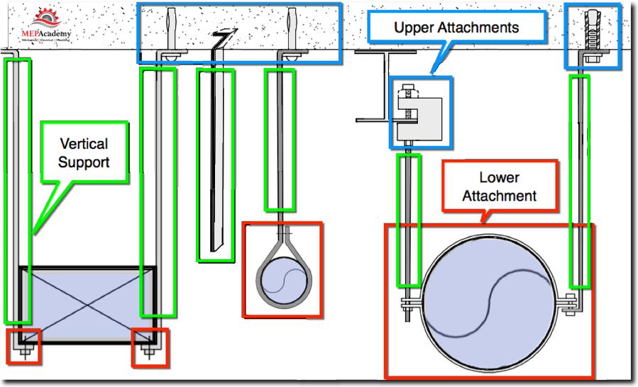
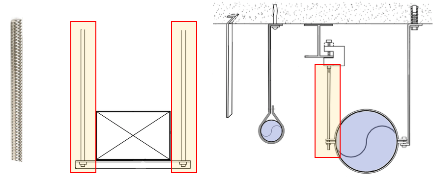
Hanger requirements vary based on locale, but will often consist of two to three parts, the upper attachment (highlighted in blue) which attaches to the structure, the vertical hanger piece (highlighted in green) and the lower attachment (highlighted in red) which attaches to the duct.
There are many different upper and lower attachment types. A few are shown here for concrete.
Hanger Upper Attachments
The upper attachment portion of the hanger attaches to the building structure. The type of upper attachment to use is conditional upon the type of structural element it will be attach to. Common materials are wood, concrete and steel beams. The hanger’s upper attachment will then be connected to the vertical support piece which most commonly is a hanger strap, threaded rod or wire. Hanger strap are made from strips of galvanized metal ranging in gauges from 16ga to 26ga
Concrete Inserts
In commercial construction, concrete is often used to construct the floors, which can be constructed in place with forms or poured onto some form of metal decking.
The concrete insert will need to be installed before the concrete is poured when using metal decking. This will require that the hanger insert (the upper attachment) be placed on the floor above where the hanger is required. For example, if you are hanging duct or piping on the first floor, you would need to put the concrete insert into the floor of the second floor. Watch the video below to get a better understanding of what we mean.
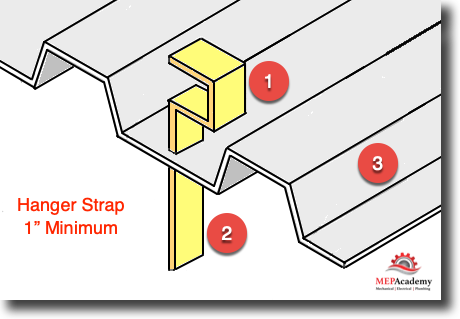
(See image below) You could use a simple bent flat bar (#1) that penetrates the floor deck (#3) and which gets covered in concrete to fix it in place. Field labor would spot the location for the hanger and punch a hole in the metal deck, then drop the sheet metal hanger through the punched hole, making the hanger available for the floor below.
With this type of hanger, the layout occurs on the floor above. This is best accomplished using some form of GPS laser layout tool, that automates the process based on CAD drawing hanger locations.
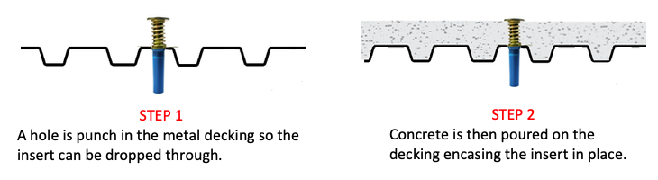
Concrete Deck Installation Procedure
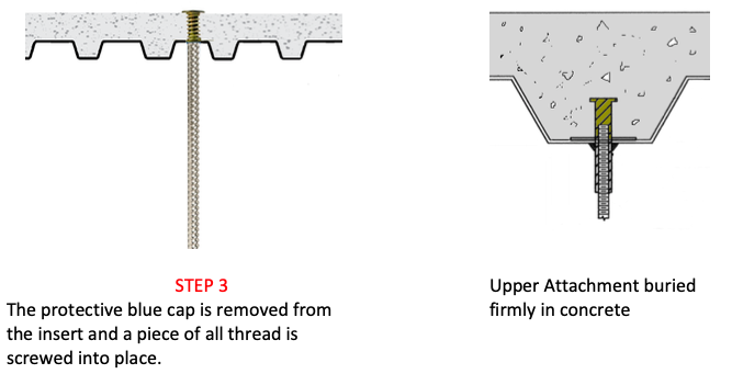
This upper attachment is inserted through a hole that is punched into a metal deck. The metal deck gets concrete poured onto it creating the solid floor. The metal deck remains in place as part of the floor assembly.
Formed in-place Concrete Floor Inserts
This hanger upper attachment is hammered into the wood forms before the concrete is poured. After the concrete has hardened and the wood forms are removed leaving the upper attachment embedded within the finished concrete floor. The upper attachment allows a threaded rod (vertical hanger) to be screwed into its exposed female threaded bottom portion.
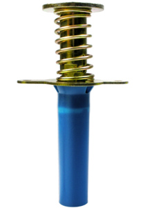
Powder-Actuated Concrete Shot Pins
When working in existing structures with concrete flooring, you might use a concrete shot pin if approved by the specifications and building ownership. This allows you to use a special powder actuated tool that shoots the upper attachment into the concrete. The tool uses a small shell filled with gun powder to force a pin into the concrete. The power-actuated shot pins should not be used in light weight concrete or concrete that is less than 4” thick.
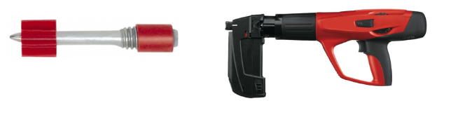
Using a powder actuated shot that shoots your hanger into the concrete is a fast and convenient way to attach your hanger. Below is the Gripple system that uses a wire instead of a strip of galvanized hanger strap, but the process is exactly the same.
Watch the below video from Hilti a major manufacture of construction tools to see a version of this tool in action.
Concrete Anchors
When powder actuated shot pins aren’t allowed you could use drilled anchors for concrete attachments. The benefit of power-actuated or drilled concrete anchors is your ability to locate them precisely where you want them from the same floor that the vertical hanger will be attached.
Expansion anchors will require the drilling of a hole for the insertion of the anchor. This process is a little more labor intensive then power-actuated shots and concrete inserts.
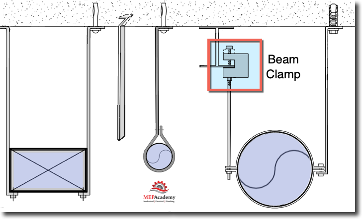
Beam Clamps
Just as the word implies this upper attachment clamps onto a structural steel beam for support of the ductwork. There are numerous types of beam clamps based on the type of structural steel support that it will attach to and the differing beam clamp designs by the various manufactures.
The Gripple beam clamp shown in the video below is used with their proprietary hanger system that uses wires with a quick fastening, locking mechanism.
Wood Rafters
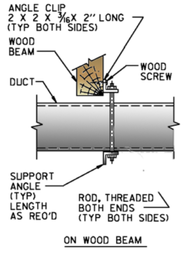
Various commercial construction projects and lots of residential projects are build out of wood. There are different ways of hanging duct from the wood structure, the easiest being a hanger strap nailed to the wood beam, but if your duct is large or if the local code requires something more stringent, there are other ways of hanging duct. Here is a detail that is at the more expensive end of the methods by which to hang from a wood structure, but it gives you an idea of hanging from wood beams.
Metal Decking
There are many different manufactures that make hanger components. Here are various upper attachments for metal decks from Badger.
Wood Form Concrete Deck
This upper attachment is used where wood forms are used for the laying of concrete. The upper attachment is nailed into the wood forms so that its held in place. The concrete deck will be poured encasing the upper attachment, which will be buried in the concrete providing a very rigid support. Then from the floor below the lower attachment will be attached to the embedded upper attachment. Watch this video to see how this is accomplished.
Vertical Support Members
The most common vertical supports are either sheet metal hanger strap (strips of galvanized sheet metal) or threaded rod. Hanger strap can be made in the shop from stocks of flat sheets or it can be purchased from vendors that sell rolls or bundles of pre-cut hanger straps.
The vertical support member is based on construction standards which take into consideration the size and weight of the duct.
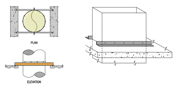
Using all-thread is usually accompanied by a piece of angle iron or Unistrut horizontal support member for under rectangular ducts and some form of half or full angle ring for round duct.
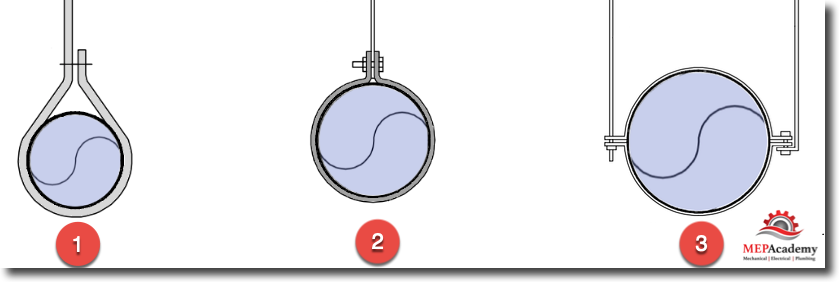
1) Here a galvanized hanger strap is looped around the duct and fasten onto itself. This vertical support and lower attachment are one piece.
2) Here is a galvanized hanger strap attached to a lower attachment that is comprised of a full circumference sheet metal band.
3) This shows you the option of using a hanger strap or rod for the vertical hanger, and a split ring lower attachment support.
You can buy sheet metal hanger strap in rolls and cut them to length or order them from a fabrication shop pre-cut to the desired length.
Lower Attachment
The lower attachment is the portion of the hanger assembly that attaches to the duct. As shown above for round ductwork, this can either be a single strap of sheet metal, a full circumference ring or a split ring.
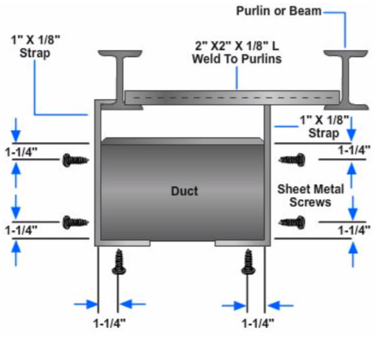
The lower attachment for rectangular duct can also use a continuous galvanized strap hanger wrapped under the bottom of the duct and fasten with sheet metal screws or rivets to the duct. For larger ductwork a vertical rod or hanger strap would be attached to a piece of angle iron, Unistrut or galvanized angle run horizontally under the duct.
Hanger Spacing
The distance between hangers is specified in the local code. The often cited reference for hanger requirements is SMACNA HVAC Duct Construction Standards. Hanger spacing in SMACNA is either every 4’, 5’, 8’ or 10’. Its best to use hanger spacing of 8’ or 10’ to maximize the span between hangers and reduce the amount of time for installing hangers.
As ducts get larger or spacing between hangers increases they will require a heavier gauge hanger or a thicker hanger rod.
For example, the following two ducts require very different vertical support materials at a 5 foot spacing interval.
Duct #1 – 60” x 16” requires a 1” wide 20 gauge strap or 3/8” rod
Duct #2 – 18” x 12” requires a 1” wide 22 gauge strap or 12 gauge wire
Things to Remember; The larger the duct or the spacing between hangers, the greater the strength of the hanger supports.
According to SMACNA, hangers are required on horizontal ducts within two 2 feet (0.61 m) of each elbow and within four 4 feet (1.2 m) of each intersection. Hangers are normally manufactured using galvanized steel strips or threaded steel rod, but in areas where there is a corrosive environment the use of electro-galvanized hangers provides additional protection.
The type and strength of the hanger is based on two important aspects;
- The spacing between hangers
- The size of the duct
The chart below shows the required vertical hanger support thickness required based on the half perimeter of the rectangular duct for the 8’ and 10’ spacing. See SMACNA table 4-1 for the 4’ and 5’ spacing requirements.
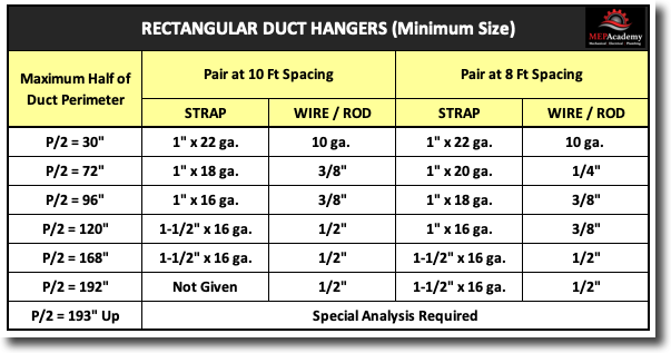
Minimum Size Hanger Example;
Duct Size = 48” x 12”. Perimeter equals P= 48 + 12 + 48 + 12 = 120”
P/2 = 120”/2 = 60”
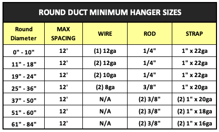
The chart below is for round duct minimum hanger sizes.
Hanger Length
If you’re using a software program for estimating than there will be a default length set in the database, usually 3 to 5 feet in length.
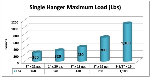
Hanger Capacity
The table below shows the maximum load (Lbs) a single vertical support member can support. (data from SMACNA Table 4-1) Starting from the bottom left we have a 1” x 22 gauge hanger strap that has a maximum load of 260 pounds, while all the way to the right of the chart we have a 1-1/2” 16 gauge hanger strap that has a maximum load of 1,100 pounds.
Trapeze Hangers for Multiple Ducts
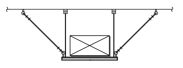
The use of trapeze hangers will require a load calculation to determine what materials will be required to support the proposed load on the hanger and its upper and lower attachments. Trapeze hangers allow for the support of multiple ducts or a combination of ducts and pipes. A structural engineer maybe required to ensure that the structure can support the weight of the items supported on the trapeze hanger assembly.
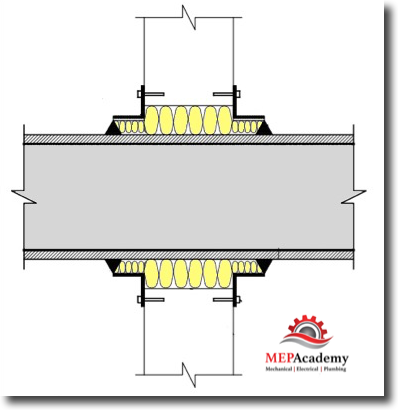
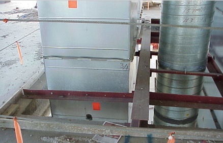
Riser Supports
When a duct rises up through multiple floors or up within a shaft it will need to be supported at each floor or every other floor, with a piece of angle or other structural element that is capable of handling the weight of the riser. The riser support can be attached to the duct with sheet metal screws, rivets, bolts or welds. The riser support will often be attached to a concrete floor with anchors, a wood floor with screws, to structural steel with welds or bolts, or embedded into the concrete floor.
Make sure to include riser supports every floor or other floor, with at least a riser support every 12 to 24 feet based on the size and weight of the duct. Angles or channel can be attached to the side of the riser duct as shown in the images below.
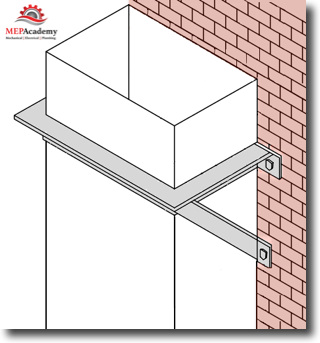
Wall Mounted Duct Supports
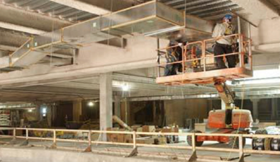
Duct running up an exterior wall will need some form of support to hold it in place. Depending on the height of the attachment some form of mechanical lift maybe required to allow a worker to safely make this connection to the structure.
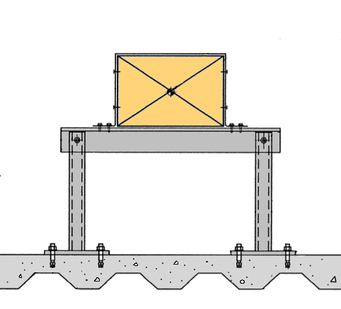
Roof Duct Supports
Ducts are commonly run on roofs because of the lack of attic space or for convenience and ease of installation.
All roof ducts will need some form of support and attachment to the structure if required, unless Dura-blok’s or similar supports are allowed. Look at page 4 of this PDF for Dura-Blok supports that are commonly specified.
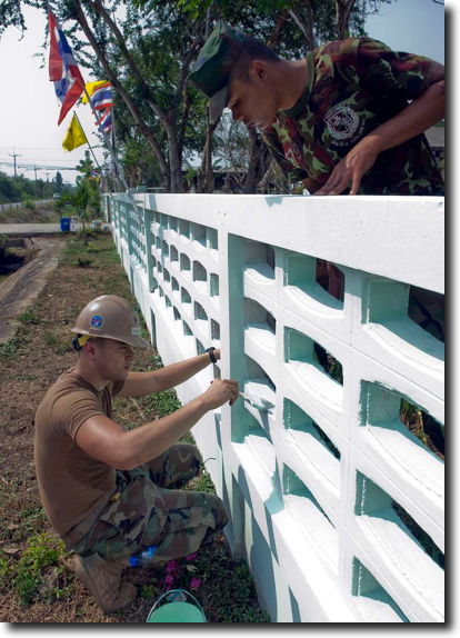
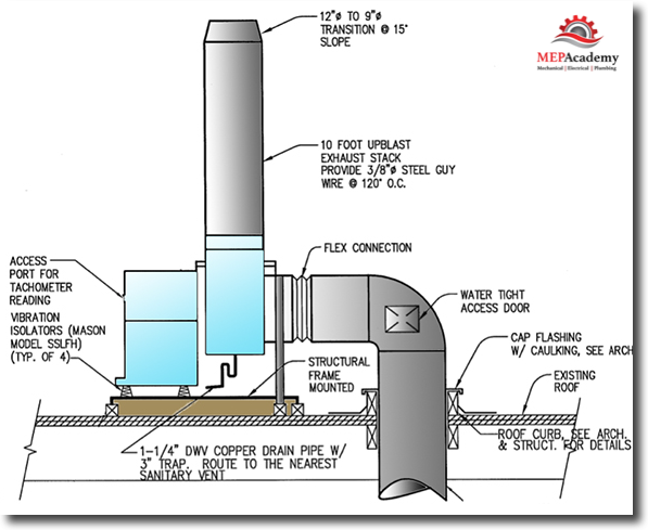
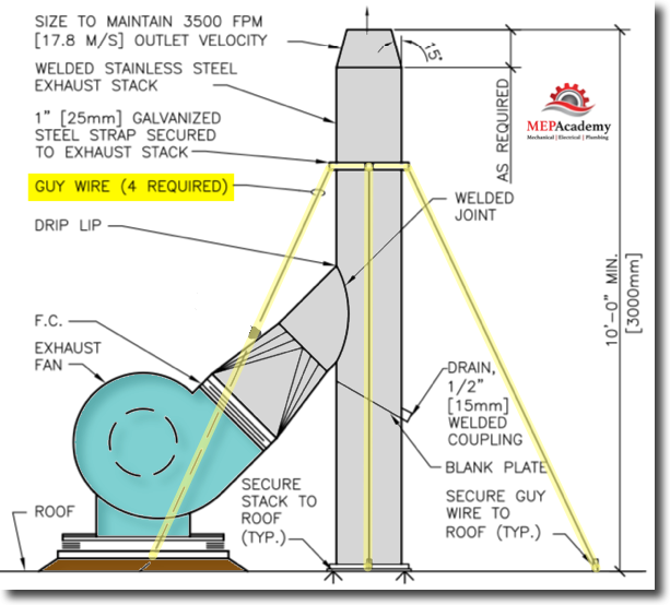
Stack Supports
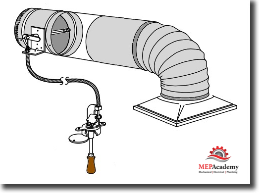
Exhaust stacks or boiler flues that extend above the roof could require some form of support. Here guy wire (aircraft cable) is used to keep the exhaust stack steady in windy weather.
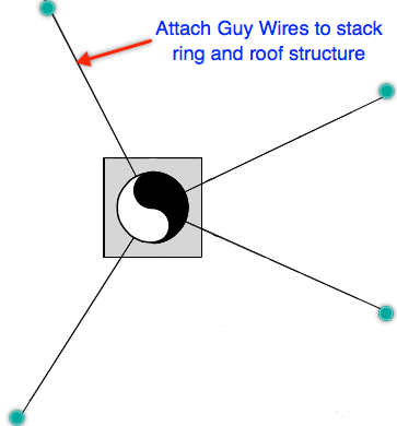
Duct Stack Support – Guy Wires
Hangers in Commercial Construction
In new commercial construction projects the type of hanger you use will be based on the materials and methods of construction within the parameters of the local code. Are the floors poured concrete on metal Decking, if so you will have a system similar to the one shown in this video.
The type of hanger you use will depend on the materials that you need your hangers to be supported from. Is the deck or floor above constructed of concrete, metal wood or some combination of materials?
Seismic Restraints
For those living in areas prone to earthquakes, equipment, pipes and ductwork might require seismic restraints. Based on the code in your area and the seismic zone that the property is located in; there are various seismic restraint requirements. Standard hangers are inadequate for seismic restraint, and will require additional reinforcement and support.
Duct Seismic
Technology for Installing Hangers
On large commercial projects it’s possible that the contractor is using the latest in technology to install hangers. Trimble is a company that has specialized in GPS systems and has created the “Robotic Total Station” for laying out hangers in less time than traditional methods.
By importing the BIM (3-D Model) drawings into the Trimble program the system will identify the exact location on the jobsite for each hanger using laser technology. Watch the video below to see this technology in action.
The use of building information modeling (BIM) and its ability to export data for use in jobsite technology tools has increased field productivity rates far above existing manual methods. At the jobsite the instrument is positioned so it can be aligned with two building site control points. This allows the instrument to precisely locate the hanger location points using distances and angles matching the design drawings.
If installing hangers without the latest technology, you would need to breakout the old tape measure and find a control point to start from and measure to each hanger location. A control point is a reference point that allows you to start from a reliable spot in the building to measure from for accuracy. This would require that you have a set of printed detailed drawings that indicate the location of each hanger and its distance from some reference point in the building.
After you locate the location for each hanger, you’ll need to install the Upper Attachment, then the lower attachment hanger assembly. If you are using concrete inserts on metal decking, then you would mark the location on the deck using the laser guided tool for precise placement of the hanger. At that point you would punch a hole in the deck for the upper attachment using a special tool.
There are various upper and lower attachments based on the type of construction (new construction or retrofit), structural element to hang from and the code required hanger materials and methods. It’s important to know what your ductwork will be supported from, such as the concrete deck above, structural beams, wood rafters or joists.
Various Manufactures Hanger Systems
Below are some additional methods of hanging ductwork that are proprietary to the specific manufactures, such as Gripple and Ductmate.
Gripple “Fast Trak”
Ductmate Clutcher
Below is Ductmates® proprietary “Clutcher” hanger system. The Clutcher hanger system meets all of SMACNA’s upper and lower attachment requirements if installed per the manufactures installation guidelines.
Gripple’s Duct Trapeze
Hanging Fiberglass Duct
Less commonly used is fiberglass ductwork. Here is a hanger system by Gripple that makes the hanging of fiberglass duct much easier than traditional methods. In this video the Gripple system competes side by side with the traditional method.
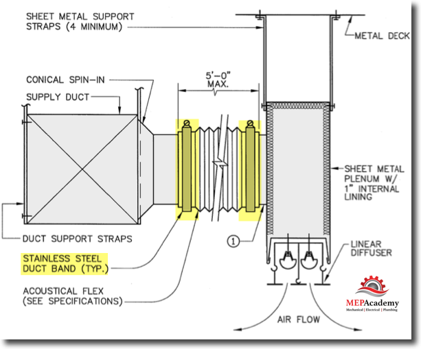
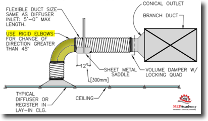
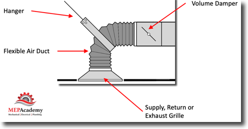
Flexible Duct Hangers
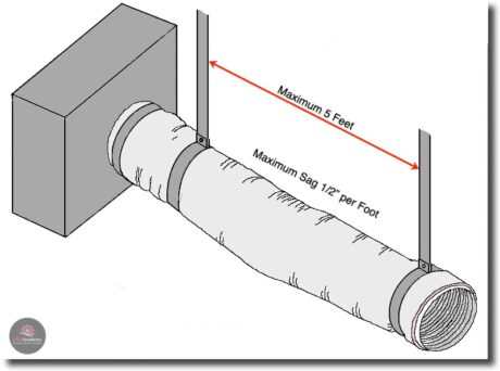
Flexible ducts require a shorter distance between hangers because flexible duct lacks the rigidity to avoid excessive sagging. Flexible duct requires a maximum distance of 5 feet between hangers, but check your local code for more stringent requirements. According to SMACNA the maximum sag is 1/2” for every foot between hangers, this means that a 5 foot maximum span between hangers would allow a maximum sag of 2-1/2 inches.
Summary
The following is what we have learned in this lesson;
- Duct is hung with up to three separate hanger pieces; the Upper & Lower Attachments, and the vertical member.
- The upper attachment used depends on the structural component that it will be attached to.
- Powered actuated tools should not be used on concrete decks less than 4” thick or made of light-weight concrete.
- The choice of hangers is driven by the local codes and specified by the engineer
- Hangers are influenced by the size and weight of the duct.
Sheet Metal Field Installation Course
- Chapter #1- Rectangular Duct and Fittings
- Chapter #2 – Round Ductwork and Fittings
- Chapter #3 – Sheet Metal Duct Hangers
- Chapter #4 – Sheet Metal Field Labor Productivity
- Chapter #5 – Labor Crew Sizes
- Chapter #6 – Sheet MetalDuct Sealer
- Chapter #7 – Sheet Metal Details and Specialties
- Chapter #8 – Grease Exhaust
- Chapter #9 – Air Distribution
- Chapter #10 – Rental Equipment
- Chapter #11 – Conditions Affecting Field Labor
- Chapter #12 – HVAC Equipment Labor