All certified boilers have a uniform test procedure to evaluate the vent system. The vent categories are determined to be either under a positive or negative pressure. They are also categorized by their possibility to condense water from the products of combustion. The ability of the products of combustion to condense into a liquid is related to the efficiency of the boiler. As the efficiency of the boiler goes up, the temperature of flue gases becomes cooler, increasing the changes of condensation.
If you prefer to watch the video of this presentation, then scroll to the bottom of the page.
Boiler Flue Vent Chart
Here we put together a simple vent chart to help you envision the requirements.
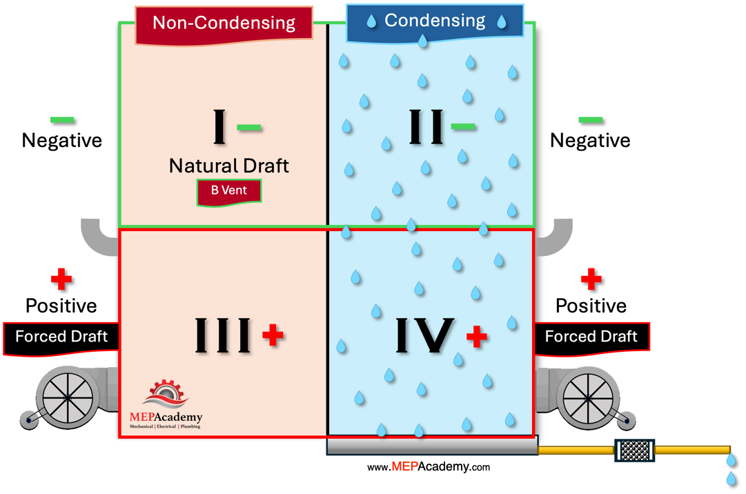
Category I Vents
The most used vent category is category One, which is where you might find the use of Type “B” vent materials. This is considered a non-condensing, negative pressure or negative draft system. Since the products of combustion are hot enough to stay above the dew point temperature there should be no condensate.
Type B Vents
Type B vents are designed specifically for non-condensing appliances that produce high-temperature flue gases not exceeding 400 degrees Fahrenheit. These vents operate under negative pressure, relying on natural draft to expel combustion gases. They are usually used with gas appliances with draft hoods.
Category II Vents
Category II vents also operates under a negative pressure like category I, but the flue gases are much cooler than a category one vent. The cooler products of combustion make the gases susceptible to condensation, so they’re located under the condensing side of the chart. Since condensation is possible, the material of the flue must resist the corrosive nature caused by the presence of moisture.
Category III Vents
Category III vents are considered positive pressure because they use a power exhauster for combustion and venting. Positive pressure vents create a unique risk because they can push combustion gases, including potentially harmful carbon monoxide, into the occupied or living space if there are leaks in the venting system.
Unlike negative pressure vents, which rely on natural draft to pull gases out, positive pressure systems actively force gases through the vent, increasing the likelihood of leakage if the venting system is not properly sealed and maintained. Since the flue gas temperature is high enough to avoid condensation, category three vents are in the non-condensing section of the chart.
When replacing a non-condensing boiler with a condensing boiler, several critical considerations must be made regarding the existing flue system. Condensing boilers operate differently than non-condensing boilers, primarily because they extract more heat from the exhaust gases, causing the gases to cool and condense before exiting the flue. The cooler temperatures my cause water to condense in the vent.
Category IV Vents
Category IV also uses a forced draft positive pressure vent, but since the flue gas temperatures can reach temperatures below the dewpoint they’re classified as condensing type. The flue will also require that the material resist corrosion caused by the presence of moisture.
Direct Venting
Specialized venting systems, such as direct venting, use sealed combustion to draw air from outside and expel exhaust gases directly outdoors, enhancing efficiency and safety. This system typically consists of two separate pipes for intake and exhaust. Direct vent systems improve efficiency by not using indoor air for combustion and minimize the risk of indoor air contamination.
In addition to enhancing efficiency and safety, direct venting systems offer several other benefits. They reduce the risk of back drafting, which can lead to the infiltration of harmful combustion gases like carbon monoxide into the living space. Direct venting also allows for more flexible installation options, as these systems can be vented horizontally or vertically, making them suitable for a variety of building layouts.
Furthermore, by using outdoor air for combustion, direct vent systems help maintain better indoor air quality and reduce drafts, contributing to a more comfortable indoor environment. Lastly, these systems are generally quieter and more aesthetically pleasing, with fewer visible exterior components.
Flue Material
A category One vent with a non-condensing boiler flue typically use double-wall type “B” vent materials. The double-wall helps maintain the flue temperature above the condensing temperature.
Condensing Boiler Flues must be made from materials that can resist acidic condensate and moisture, such as PVC, CPVC, Polypropylene, or Stainless Steel. Check the boiler manufacturers data to determine the required material. If converting from non-condensing boilers to condensing boilers then the existing metal flues may corrode due to the acidic nature of the condensate produced by condensing boilers.
Condensing boilers often require smaller flue diameters due to lower exhaust gas temperatures and higher efficiency. The existing non-condensing flue size may need to be reduced to maintain proper draft.
Condensing boilers produce significant amounts of condensate that must be safely drained away. The condensate is acidic and may require neutralization before being discharged into the drainage system to prevent damage to plumbing and the environment.
Summary
When replacing a non-condensing boiler with a condensing boiler, it is essential to thoroughly assess and potentially modify the existing flue system to accommodate the specific requirements of the condensing boiler. This includes using appropriate materials, ensuring proper sizing and configuration, managing condensate, complying with codes and regulations, and potentially insulating and sealing the flue system.