Chapter #8 – Estimating Summary Sheet
We will use the MEP Academy Estimating Spreadsheet for all our examples. Hopefully the estimating spreadsheet your company uses is as versatile, if not, maybe you could suggest they purchase the MEP Academy Estimating Spreadsheet. This section of the course will cover the front page of the estimating spreadsheet which summarizes the totals from all the individual pages, plus provides some important metrics.
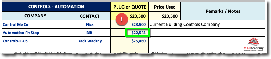
After completing all other task, it’s time to put any values you already have into your spreadsheet to get an idea of the magnitude of the project. Be sure to identify clearly what contains a plug number. Most of your plug numbers will be for HVAC equipment pricing and subcontractor cost. This should be done at a minimum of two days before the bid is due, never on bid day, which can be very hectic.
The plugged numbers will also help you in determining the bid bond amount if required. Remember plug numbers are based on historical cost data that you have saved for just this purpose.
Be sure to have your bid bond ready to go if required.
If the price has to be sealed in an envelope and delivered within a certain time, be sure to have the envelope addressed as required and ready with all bid documents filled out ahead of time, except for the price. It may even require stationing someone with a cell phone at the bid drop off location on the day, and right before the closure time for responsible bidders.
Project Set-Up
The MEP Academy Estimating Spreadsheet has several sections, but at the top of the spreadsheet is where you will put the project information.
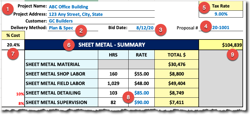
Begin by typing in the name and address (#1) of the project, delivery method (Design-Build, Design-Assist, Plan & Spec)(#2) and the bid date (#3). Add the proposal number (#4) to keep track of all your proposals and the Tax Rate (#5) for the city or location of the project.
Sheet Metal Summary
The Sheet Metal Summary (#6) brings forward all the totals from the Sheet Metal Material and Labor Summary sheet along with the Sheet Metal Specialties sheet and equipment labor related to the sheet metal trade.
Also shown is the percentage (#7) of the total cost attributed to the Sheet Metal trade. Everything that is shown in a bright blue font is editable, the rest of the cells are protected. You will need to enter the labor rates for the detailer and for supervision (#8). The total material and labor cost for the sheet metal trade is shown in item (#9).
Piping & Plumbing Summary Sheet
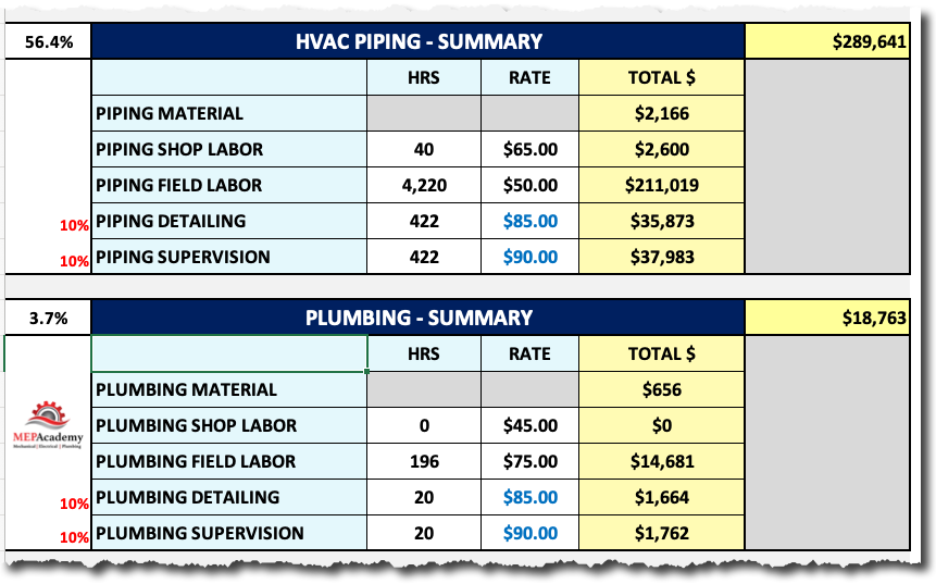
For those companies that provide HVAC Piping and Plumbing in their business, there are separate sheets within the MEP Academy Estimating Spreadsheet that can be used. These summaries are similar to the sheet metal summary section as they bring forward the total material and labor from the trade tabs of the spreadsheet.
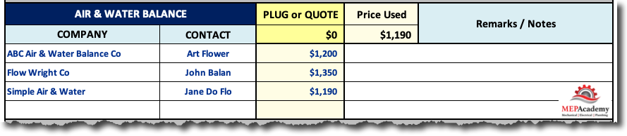
Air & Water Balance/Start & Test
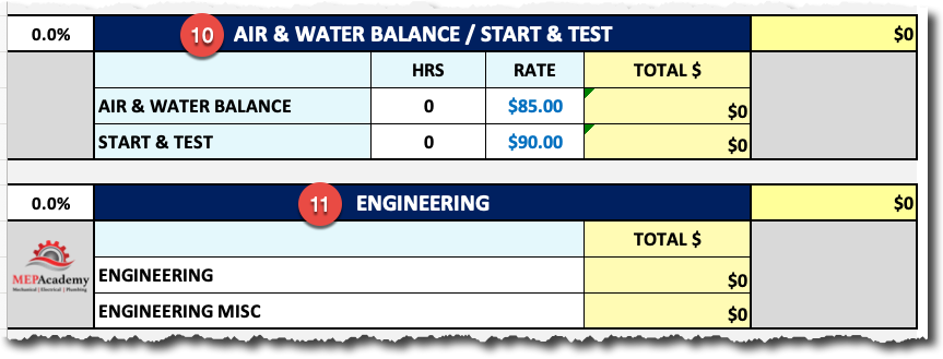
If the specifications allow and your company has the capacity to perform their own Air & Water Balance (#10) there would be a value shown here on the front of the spreadsheet. Most plan and specification project usually require a 3rd party company to do the air & water balance to avoid any appearance of a conflict of interest.
Engineering
The engineering summary is for those projects where you are responsible for the engineering and design. In a plan and spec delivery format this wouldn’t be required, as the drawings and specification have already been completed by a 3rd party mechanical engineer.
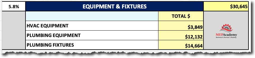
HVAC & Plumbing Equipment & Fixtures
This section provide the total cost for the HVAC & Plumbing equipment in addition to the plumbing fixtures. Remember that all these values are summaries from other pages in the estimating spreadsheet. Everything is just summarized on the Final Estimate Summary Page.
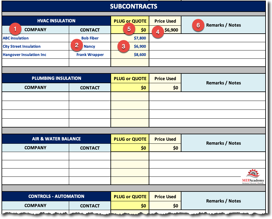
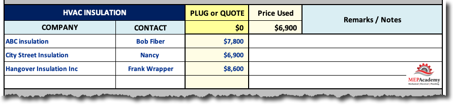
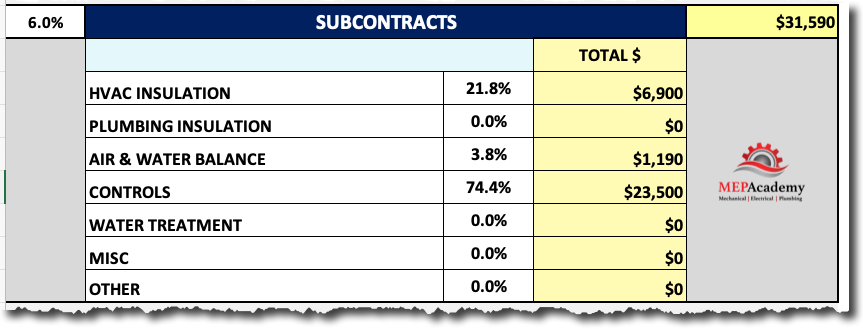
Subcontractors
Once again this is just a summary of your subcontractors page for all the HVAC and Plumbing Subcontractors for this project.
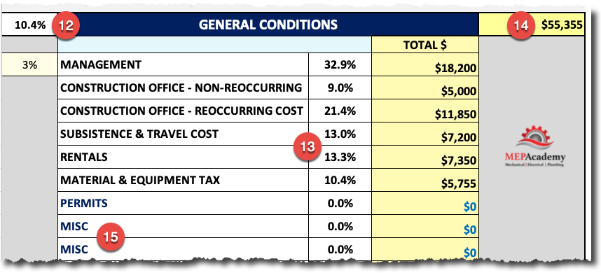
General Conditions
Most of these cost come from the General Conditions tab of the MEP Academy Estimating Spreadsheet. Item #12 shows what percentage general conditions are to the total cost, while item #13 shows what percentage the particular line item general condition is to the total General Conditions cost (#14). Also there are additional line items for anything the user would like to add. This gives a quick overview of the general conditions cost on the front sheet.
Contingency, Margin and Sales Price
After reviewing all of the above, now it’s time to make the decision on how much contingency to carry and how much profit and overhead to add to your bid.
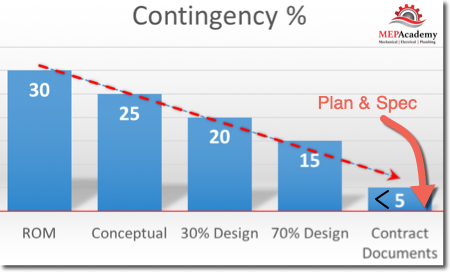
Contingency
You can think of contingency as cost that could occur, but is not certain to occur. Contingency is to cover unforeseen cost that could reveal itself during construction. Contingency covers the risk associated with the unknown and is greater in underdeveloped drawings. When bidding on plans and specification type projects the contingency factor should be at the lower end of the spectrum, because the 3rd party engineer is taking the liability of showing and describing what is needed, and if anything is missing or incorrect then a justified change-order should be allowed to set things right.
Theoretically you shouldn’t need a contingency factor on a plan and spec project, but if you’re not fully comfortable with your own accuracy of a complete bid, then adding a small percentage could give you a better night’s sleep and provide for a small margin of error on your part.
With the MEP Academy Estimating Spreadsheet it’s easy to add a contingency factor (#17), just choose what the percentage you would like to add and the spreadsheet will automatically calculate the amount based on the subtotal cost (#16).
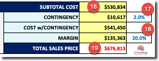
In the example above you can see that a 2% contingency (#17) added to the subtotal cost (#16) equals $10,617. From this new total you will choose the margin percentage (#18) that you want. The margin is where you recover your overhead and hopefully make a profit.
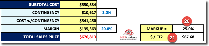
Alongside the margin is the markup which shows a much higher percentage (#20) as they are based on different formulas. What’s the difference between margin (#18) and markup (#20)? The margin informs you of what percentage the margin is to the total sales price, while the markup percentage is what you multiply the cost by.
Margin = $135,363 / $676,813 = 20% ($541,450 / (1 – Margin Percentage) = $541,450/0.80
Markup = $541,450 x 25% = $135,363
Project Metrics
The first metric is the cost per square foot (#21) shown above. This is a useful number for price checking or budgeting of future similar projects.
Your estimating spreadsheet should be capable of providing you with the various metrics that allow you to price check engineering and cost parameters.
If you’re using the MEP Academy Estimating Spreadsheet then indicate the building type and the square footage (#22) of the area being conditioned or developed. Square footage will be used to calculate the different parameters for analysis, such as Cost per Square Foot (#21), while the quantity of stories will help you compare this project to similar projects in your historical database or future projects.
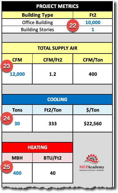
Total Supply Air CFM (#23)
By entering the total supply air CFM this will give you two important engineering metrics that can help you when budgeting. For example if you had another similar building that was in its conceptual phase, where there is no design yet, this would allow you to come up with the total CFM and tonnage based on only the square footage of the proposed building.
Cooling Metrics (#24)
This is similar to CFM, except that this will also give you the cost per ton for the project, which again is very useful when doing quick budgets without the design being completed or as a quick check figure.
Heating (#25)
Another engineering metric that maybe useful in the budgeting of the heating system for a similar building that hasn’t been design yet, but for which the owner or General Contractor would like a budget based on the conceptual drawings and the total square feet of a proposed building.
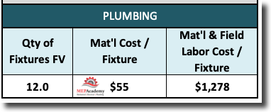
Plumbing Metrics
The MEP Academy Estimating Spreadsheet also has plumbing metrics that measures material, or the material & labor cost per fixture.

Understanding the MEP Estimating Spreadsheet (Free Course)
- Chapter #1 – HVAC Equipment
- Chapter #2 – HVAC Quotations
- Chapter #3 – Subcontractors
- Chapter #4 – Sheet Metal Material and Labor Summary
- Chapter #5 – Labor Rates
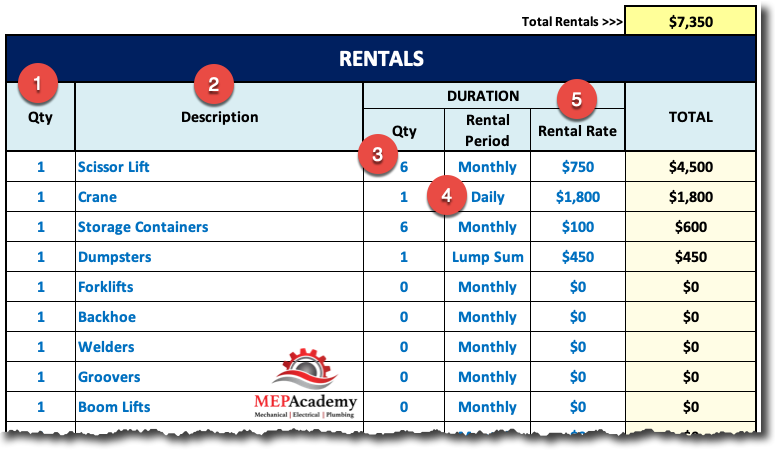
- Chapter #6 – Rentals
- Chapter #7 – General Conditions
- Chapter #8 – Finalizing the Estimating Spreadsheet
Purchase the MEP Academy Estimating Spreadsheet here >>> MEP Academy Spreadsheet