Chapter #7 – Sheet Metal Shop Drawings
Shop drawings should be created by someone in the company familiar with detailing. Detailing is the process of taking the engineered set of drawings and converting them into shop drawings that the field will use to install the sheet metal.
Sheet Metal Detailer
The sheet metal detailer’s job is to coordinate the layout of the ductwork with all other trades in order to avoid collisions or conflicts. This position is held by a union member for companies that are signatory to a local Sheet Metal Union. Their job is to ensure that the sheet metal fits within the space and to show all the required dimensions on the drawing so as to make the field installation go smoothly and without wasting ductwork and fittings because they don’t fit into the space shown on the drawings.

The shop drawings will show the ductwork exactly where it needs to be installed in order to avoid building components and other trades.
The sheet metal detailer will review the architectural, structural, electrical, plumbing and other trade drawings in an effort to avoid installing ductwork where these trades have their systems and where structural supports and architectural items are to be installed.
Detailed Shop Drawings
Looking at the sheet metal shop drawing below you can see that additional items are shown on these drawings compared to the engineered set. These drawings are drawn in CAD (Computerized Aided Drawings), which is drawn on a special computer program. If you have a small project then using CAD may not be feasible, and in this cases the detailer will just fill out the sheet metal fabrication shops order forms directly from the engineered set of drawings and from what is discovered during a site visit for existing buildings.
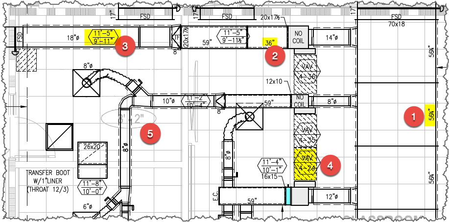
The numbers in the red circles correspond to the following;
#1 (Duct Size & Joint Length) This shows that the rectangular duct that is 70” x 18” in size is 56 1/4” in length. This duct is made from a 5 foot (60 inch) coil width, and the difference is from the joint. 60” coil width – 3 3/4” joint (1-5/8” each joint) = 56 1/4” in length.
#2 (Plenum Size & Length) This is the plenum off of the VAV box, which is a duct that is 20” x 17-1/2” in size by 36” in length.
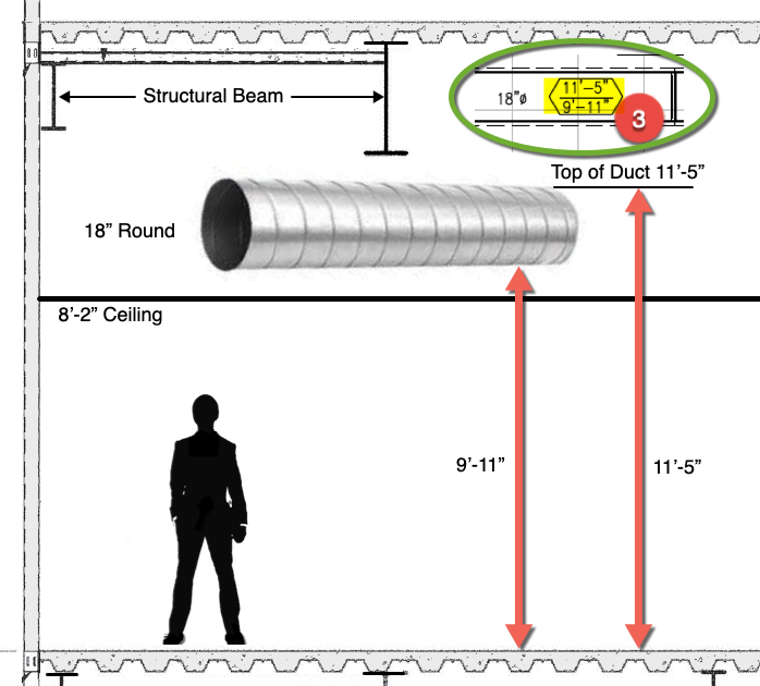
#3 (Duct Elevation) This shows the bottom and top elevation of the ductwork. This shows that the bottom of the duct is 9’-11” off of the floor, and that the top of the duct is at 11’-5” off of the floor.
#4 (Service Access) – According to the manufacture or local code authority, each piece of equipment, valve or accessory that needs adjustment or service is required to have an unobstructed access area. As shown in item #4 the hatched area next to the VAV boxes must be kept clear so that a service technician can access the controller.
#5 (Ceiling Height ) – The height of the ceiling is indicated to be 8’-2”
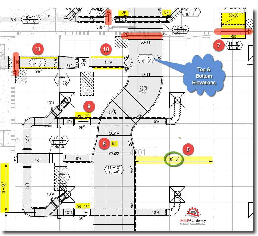
#6 (Benchmark Distance) – The location of the edge of the ductwork is indicated as being 10’-0” from the column line.
#7 (Wall Opening) – Top and Bottom elevation of Return Air Boot opening in Fire-Rated Wall, as can be seen by the Fire/Smoke Damper.
#8 (Direction) – BF = Bottom Flat. This is a transition fitting that is changing the size of its depth. In order to inform the fabrication shop and the field installer which side remains flat these acronyms are used. It’s also possible to install a concentric transition, where both sides converge evenly.
#9 (Duct Offset) – This indicates that the duct needs to drop by 16” in order to get under the large main supply air duct. It’s important to remember this when you are working with a set of engineered plans that haven’t been detailed into shop drawings. Remember to add extra fittings when crossing ducts.
#10 (External Insulation Wrap) – The dotted line on the outside of the duct indicates that this ductwork will get wrapped with insulation, most likely by your insulation subcontractor.
#11 (Internal Liner) – These dotted lines on the inside of the duct indicate that the ductwork is lined with acoustical liner.
From Shop Drawing to Fabrication Equipment
From the shop drawings the detailer will either draw the required duct and fittings onto an order form or the CAD software will download the information to the shop fabrication equipment with or without the shop superintendent’s modifications.
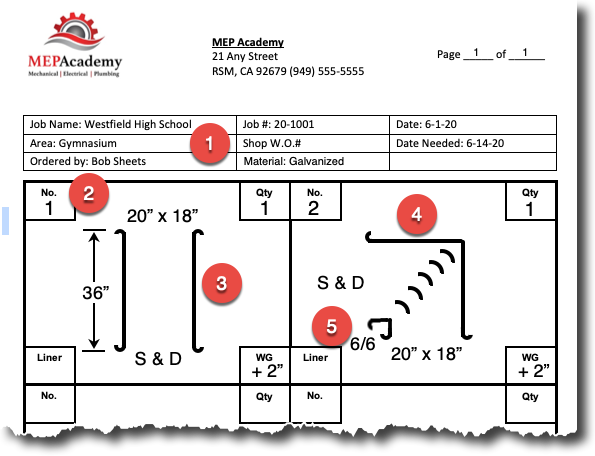
For those that have an integrated software system where the CAD drawings can be directly sent to the fabrication equipment, this will save a lot of time by not having to draw out each piece required to be fabricated or enter data into the coil line or plasma cutter.
Detailing for Retrofit Projects
Detailing for existing buildings can be done in a similar manner as that of new construction, except that you will need to do a site survey to document what is in the space where new sheet metal or HVAC equipment will need to be installed. Again, based on the size of the project and the requirements of the RFP (Request for Proposal) the use of CAD may or may not be used.
For small retrofit projects the detailer will visit the project site and make the measurements required to get the needed ductwork and fittings fabricated. There is no need to go through the expense of drawing everything in CAD.
Control / Reference Point
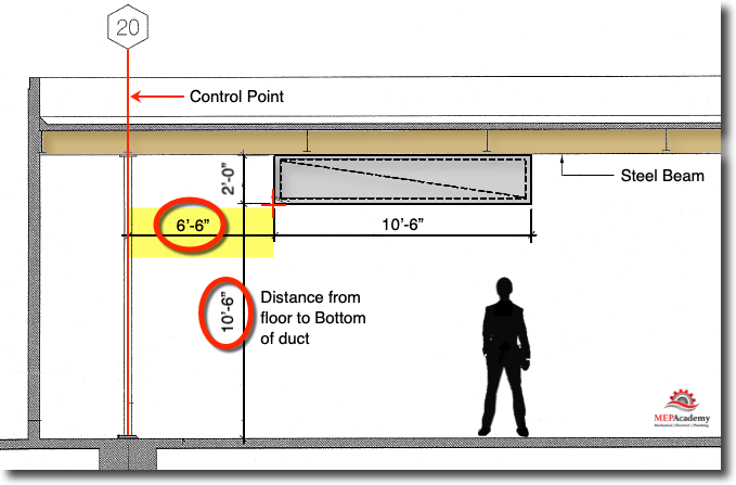
The construction project will have one or more control points from which everything can be measured from in order to ensure the accurate location of walls and other trades. The control point is determined by a field engineer and has an X, Y, Z reference point.
Navisworks by Autodesk (Collision Detection)
Most large new construction projects are built within some form of modeling software like Autodesk Revit, Bentley or many others.
In the enclosed video at about the three minute mark you will see that the Navisworks software will pick up a collision between a sheet metal duct and a structural beam. Navisworks combines the different designs from the various trades (Architectural, Structural, HVAC, Electrical & Plumbing) and combines them together, and then searches for clashes that occur between them. Clashes occur when two different designers are trying to occupy the same space in the building, like the duct that is placed where a structural beam is located.
Using Autodesk Navisworks helps eliminate change orders and costly field errors by finding them before they get installed.
Shop drawings are done in AutoCAD, Autodesk Revit MEP or some other modeling software that allows for the coordination with other trades using Navisworks to ensure that the sheet metal will fit within the building without hitting anything.
BIM (Building Information Modeling)
The use of BIM is widely used throughout the industry for commercial contractors doing new construction projects. Often the requirement to use BIM is specified in the design criteria for many Federal, State and local Municipalities in addition to the private sector. BIM make coordination easier and reduces the amount of change orders due to the collision checking before construction begins.
The sheet metal estimator will need to provide hours in the estimate to cover the detailing requirements per the RFP (Request for Proposal) or ITB (Invitation to Bid). If there are no requirements then your companies minimum level of detailing required to accomplish the ordering of ductwork and fittings.
Companies that maintain historical data from completed project will be able to look at metrics from those projects which could help determine the hours required for the current project. A metric like, percentage of detailing hours to total field hours would be helpful.
10% Detailing (historical data feedback)
Example: Current Project has 2,000 field labor hours.
Calculate detailing: 2,000 Field Hrs x 10% = 200 detailing hours
Below is a screen shot of a small section of the Sheet Metal Material & Labor Summary tab of the MEP Academy Estimating spreadsheet that allows you to enter a percentage of your total field labor for detailing.

Summary
The detailer will create shop drawings by reviewing the location of all the architectural, structural, electrical and plumbing elements in addition to the various other trades that require space within the building for their component.
The detailer will coordinate with the other trades to ensure that everything fits within the space allotted. It’s possible that software like Navisworks will be used to detect collisions automatically within the software program, thereby minimizes field change orders.
Detailing can be done on a computer using some form of CAD, or on smaller project detailing can be done by hand and drawn out on an order form.
Detailed drawings (shop drawings) shows the size, length and duct joint information for each piece of ductwork and fittings, along with their elevation height.
- Chapter #1 – General Layout of Drawings
- Chapter #2 – Architectural Drawings
- Chapter #3 – Plan, Elevation, Section Views and Details
- Chapter #4 – HVAC Mechanical Drawings
- Chapter #5 – Understanding HVAC Symbols
- Chapter #6 – Drawing Scales (How to Read Scales including Metric Scales)
- Chapter #7 – Sheet Metal Shop Drawings


