Are you seeing low suction pressure on your gauges and wondering what’s going on inside the refrigeration or air conditioning system? Low suction pressure is one of the most common indicators that something’s not right — and if misunderstood, it can lead to compressor failure and costly downtime. In this article, we’ll break down the causes of low suction pressure, how to diagnose it properly, and what steps to take to correct it.
Today we’re diving deep into the causes and consequences of low suction pressure in HVAC and refrigeration systems.
What is Suction Pressure?
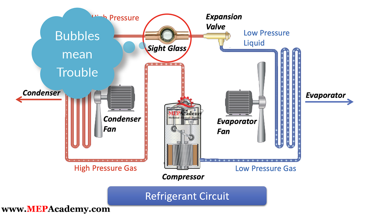
Suction pressure refers to the pressure of the refrigerant vapor entering the compressor from the evaporator. This pressure tells us a lot about what’s happening on the low side of the system — particularly in the evaporator coil and the refrigerant lines leading back to the compressor.
In most air conditioning and refrigeration systems, normal suction pressure typically ranges between 60 to 85 psig (4.1 to 5.9 bar) for R22, or 120 to 145 psig (8.3 to 10 bar) for R410A, or 115 to 145 psig (7.9 to 10 bar) for R32 depending on the system and ambient conditions.
When this pressure drops too low, it usually means the system isn’t absorbing enough heat — but the reason why can vary.
Symptoms of Low Suction Pressure
Here are some telltale signs of low suction pressure:
Suction gauge reading abnormally low. Frost or ice on the evaporator coil or suction line. Poor cooling performance. Compressor running longer than usual. Hissing or bubbling sounds from the evaporator
These symptoms mean it’s time for a diagnosis.
Common Causes of Low Suction Pressure
1. Low Refrigerant Charge (Undercharge)
This is the most common cause. If the system is undercharged — due to a leak or improper service — there won’t be enough refrigerant in the evaporator to absorb heat, leading to reduced pressure at the compressor inlet.
Check for leaks at joints, coils, and service valves. Use an electronic leak detector, soap bubbles, or UV dye.
2. Restricted or Blocked Filter Drier or Capillary Tube
A clogged filter drier or metering device reduces refrigerant flow into the evaporator, starving it of refrigerant. Less evaporation means less vapor returning to the compressor — hence low suction pressure.
Look for a significant temperature drop across the filter drier — it shouldn’t exceed 3°F (1.7°C).
3. Faulty Expansion Valve (TXV/TEV)
If a thermostatic expansion valve (TXV) is malfunctioning — sticking closed or sensing incorrectly — it won’t deliver enough refrigerant to the evaporator.
Check the sensing bulb placement and charge. Also, feel for a frost line just after the TXV outlet — that’s a red flag.
4. Evaporator Coil Issues (Frozen, Dirty, or Undersized)
If the coil is dirty or iced over, airflow is restricted. This means less heat is absorbed by the refrigerant, resulting in reduced vaporization and lower suction pressure.
Inspect coil cleanliness and ensure proper defrost cycle operation if it’s a freezer system.
5. Poor Airflow Across the Evaporator
No matter how perfect the refrigerant charge is, if there’s not enough warm air crossing the evaporator coil, you’ll get poor heat absorption.
Check air filters, fan motors, belts, and blower speed settings.
6. Oversized Metering Device or Undersized Evaporator
An oversized TXV can allow too much refrigerant into the coil, leading to potential floodback — but paradoxically, if it’s underfeeding due to poor sensing, suction pressure drops. Likewise, an evaporator too small for the load won’t provide enough heat absorption.
7. Compressor Valve or Mechanical Problems
While rare, leaky compressor valves or worn internals can cause low suction pressure and poor compression ratio.
Listen for unusual compressor noise and check amp draw.
Diagnostic Checklist
Use this quick checklist when diagnosing low suction pressure:
| Symptom | Test | Corrective Action |
| Low pressure, poor cooling | Leak test, weigh refrigerant | Recharge and repair leak |
| Frost on suction line | Inspect airflow, TXV, coil | Defrost coil, clean filters |
| Pressure drop across drier | Temp readings, IR scan | Replace clogged filter drier |
| Low superheat | Measure SH/SC | Adjust or replace TXV |
Superheat and Suction Pressure
Don’t forget — suction pressure alone isn’t enough. Always compare it with the superheat reading. Low suction pressure with low superheat might mean flooding or a bad TXV. Low suction with high superheat typically points to a starved coil.
Summary and Takeaways
Low suction pressure is a symptom — not the problem. Whether it’s a refrigerant issue, airflow problem, or restriction in the system, your job as a tech is to dig deeper and find the root cause.
Check refrigerant charge. Inspect airflow and evaporator conditions. Test metering device function. Use superheat readings to confirm diagnosis