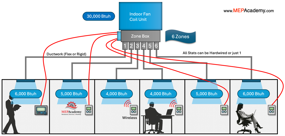
How do you serve several small zones with one Variable Refrigerant Volume (VRV) split system without adding additional indoor fan coils, and still provide individual temperature control? Currently to achieve individual temperature control you might need separate fan coils for each room with the ability to control air flow. This is where the Daikin Zoning kit can help.
Would if the building has a bunch of small spaces too small for the smallest VRV indoor fan coil unit? Then the use of air volume dampers to divide up the capacity into smaller zones works best in these scenarios. With the use of the Daikin Zoning kit, the ability to serve small areas is better achieved. This is because zone dampers divide up the air from a single indoor fan coil to serve each space. Daikin’s Zoning Kit eliminates the need for multiple indoor fan coil units to create individual zones. This should save money.
This allows smaller spaces to be served and individually controlled. The smallest available indoor fan coil is currently 7,500 Btu/h. If your space required less than 7,500 Btu/h, then you would have a couple of options.
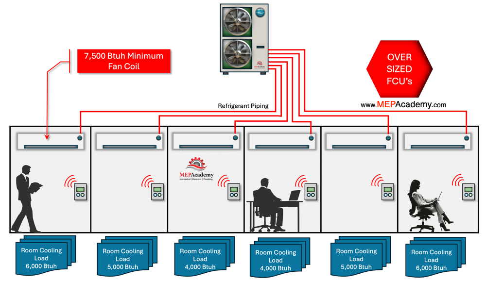
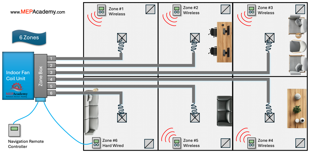
One would be to install an oversized indoor fan coil unit for the space or share the air with a fan coil that serves multiple rooms, leaving the room with a lack of individual control. There is the option to have up to 6 separate zone dampers supplying variable air flow to each zone based on the demand.
Daikin Zone Damper Box Construction
The zone kit is basically a sheet metal plenum with zone dampers attached at one end, while the other is attached to the indoor fan coil. The individual zone dampers respond to the demand from the corresponding controller in each space.
Controls and Thermostats
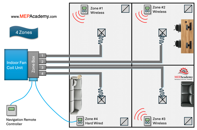
Each individual zone damper has a zone thermostat that controls the air flow to the room. The thermostat allows for on/off function, schedule control, temperature set point, touchscreen interface and sleep function. The zone thermostats use 915 MHZ wireless communication and 2 AAA batteries.
There is also a Main Thermostat with a wired color touch display that is used to configure the zone damper kit and can be used as a room controller. An add on BACnet gateway module allows the control of individual rooms using BACnet/IP compatible building management system. The main thermostat uses AWG 20 – 4 wire (shielded) communication cable supplied with 12 VDC from the main control box. This main controller can control all the zones, eliminating controllers in each zone, while still allowing each zone to have individual set point capabilities.
Hardwired Thermostats
There must be at least one hard wired controller to the control box mounted on the Daikin Zone Kit. The other controllers will communicate wirelessly to the control box which can be up to 164 feet line of site distance from the wireless controllers. There is the option to also hardwire all zone controllers if preferred or if wireless communication is troublesome. In this case, the total wiring allowable for each terminal is 130 feet.
Electrical Power
The DZK control box will need 120/240 VAC power. The control box has an alarm input that allows for an alarm to be used to shut down the fan coil and close all zone dampers. Each of the zone dampers are powered by 12 VDC from the control box.
An interface board provides communication between the zoning control board and the indoor fan coil via the NAV controller.
Lastly, there is the ability for their intelligent Touch Manager (iTM) using the BACnet Client option to provide individual room control.
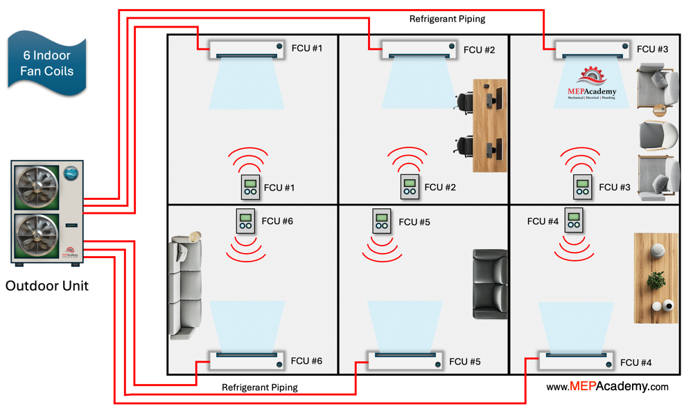
You can use the DZK with a VRV Heat Pump or Heat Recovery system. See our video on the differences between a VRF Heat Pump and VRF Heat Recovery system.
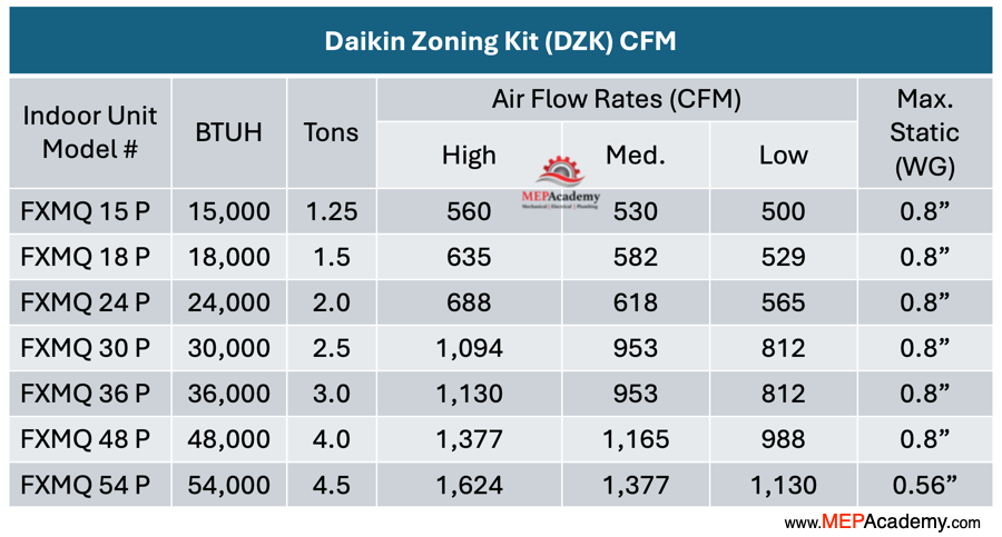
Compatible Indoor Fan Coils and Capacities
The Daikin zoning kit can be attached to a compatible ducted indoor fan coil unit that ranges in capacity from approximately 15,000 Btuh to 54,000 Btuh and contains anywhere from 2 to 6 zones. So, depending on the capacity of your indoor fan coil, Daikin provides up to 6 zones with their zoning kit. With the largest indoor unit of 54,000 Btuh this allows the option between 2 to 6 zones, depending on the size of each zone.
There are 4 different zone damper configurations to choose from, and 7 compatible indoor fan coils. The zone damper kits come in 4, 5 and 6 damper configurations. This allows anywhere from 2 to 6 zones to be configured. This allows more than one damper to feed larger zones by combining dampers or allows one damper to serve multiple air distribution outlets.
Air Balancing
The air entering the fan coil is offset from the center of the zone box. This causes some of the zone dampers to receive less air than others. This is particularly relevant with the smaller DZK030E4 & E5 models. This causes a non-uniform air velocity, and the center dampers receive more air, while the outside dampers receive less. If all zone dampers are not required, then they can be blanked off. There must be a minimum of two zone dampers used.
Key Benefits of using the Daikin Zoning Kit
- Avoid adding indoor fan coils to achieve individual zone control.
- The ability to serve an area that is smaller than the smallest VRV indoor unit.
- Increased comfort with individual control.
- Increase in the VRV systems ability to meet the demand of smaller spaces.
- A reduction in the amount of refrigerant required.