


In this article we’ll cover the basics of thermal energy storage systems. Thermal energy storage can be accomplished by changing the temperature or phase of a medium to store energy. This allows the generation of energy at a time different from its use to optimize the varying cost of energy based on the time of use rates, demand charges and real-time pricing. Utility incentives could also be available to reduce the upfront cost of installation.
By running chillers at night when the electrical rates are less than daytime rates, the operational cost of the facility can be reduced.
if you prefer to watch the Video of this presentation, then scroll to the bottom.
Thermal Energy Storage (TES) Strategies
There are two basic Thermal Energy Storage (TES) Strategies, latent heat systems and sensible heat systems.
Chilled Water Thermal Stratification (Sensible Heat)
Stratification is used within the tank as a strategy for thermal layering of the stored water. Colder water is denser and will settle toward the bottom of the tank, while the warmer water will naturally seek to rise to the top.
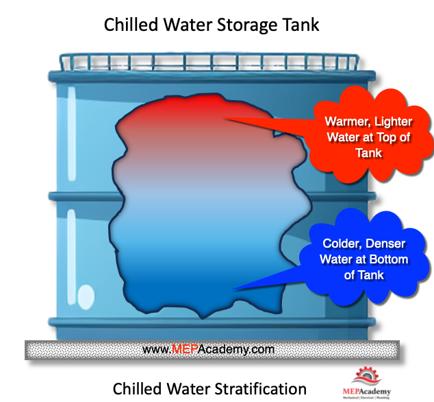
As water enters and leaves the tank it’s important to make sure not to disturb or mix the stratified layers. This is done with the use of diffusers within the tank on the inlet and outlet piping.
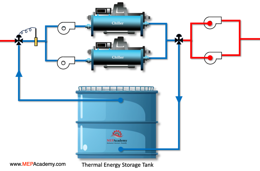
Charging the Tank
When charging the tank, the warm water is taken from the top of the tank and sent to the chiller, while the chilled water is returned to the tank near the bottom.
Tank Size Requirements
Chilled water storage tanks require a large footprint to store the large volume of water required for these systems. Approximately 15 ft3/ton-hour is required for a 15F (8.3C) temperature difference. The greater the delta-t of the water, the smaller the tank can be. Tanks can store millions of gallons of water or much smaller amounts.
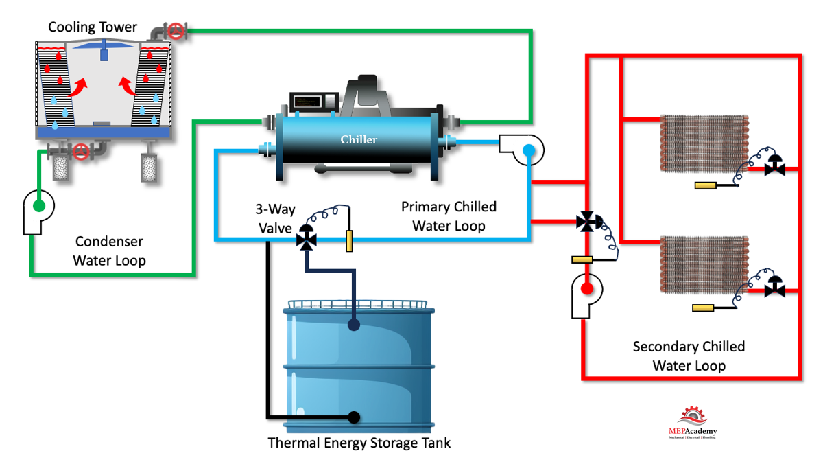
There are dozens of various layouts for thermal energy storage system, but we’ll cover the basic theory for its use.
In the image above there is the typical primary chilled water loop that produces the chilled water. Then there is the condenser water loop that uses a cooling tower to reject the heat to the atmosphere. A secondary loop that feeds chilled water to the air handler coils. And the last piece is to add in the thermal energy storage tank tied into the primary chilled water loop.
The system can run using just the chillers, or the chiller could be run at night to charge the storage tank when electrical rates are cheaper. The three way valve will close forcing the chilled water to go through the tank. While during the day when the electrical rates are higher, the chilled water can be pulled from the tank in a full storage system, and sent to the air handler coils without the use of the chillers. Partial storage systems use the stored chilled water to supplement the main chiller equipment when they have reached their full capacity and additional cooling is required.
Ice Storage Systems (Latent Heat)
Latent heat transfer strategies are more complex. There are several strategies for producing ice, one of which is to circulate a glycol solution through coils submerged within the tank. Ice then accumulates on the outside of the coil within the tank.
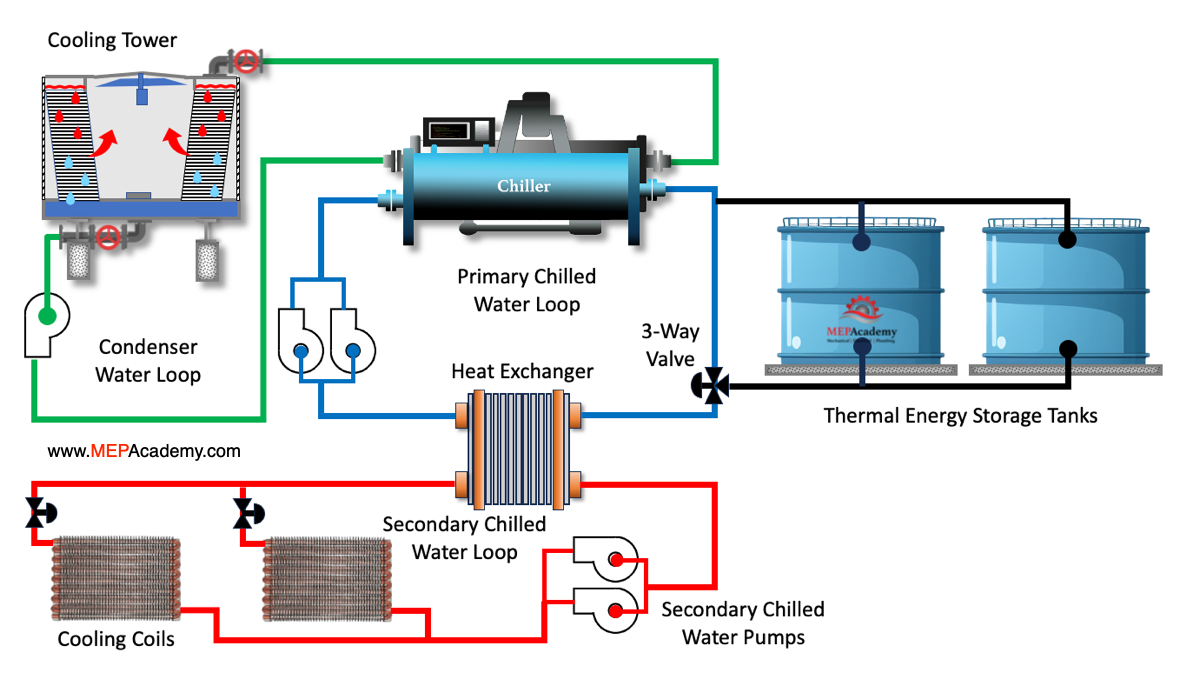
In this image we have the same water loops as the chilled water storage tank system. There is the primary chilled water loop, condenser water loop, and secondary chilled water loop. The difference with this system is that a glycol solution will circulate through the system in order to produce ice on the coils within the tanks. Glycol prevents the water from freezing. A heat exchanger will separate the primary and secondary loops. The three way valve and control sequence will control the flow of water to and from the tank..
Ice storage systems take less room for storage than chilled water systems. This is because of ices greater capacity to store energy per unit area. The storage volume ranges from 2 to 4 ft3/ton-hour for ice systems, compared to 15 ft3/ton-hour for a chilled water.
The application for energy storage systems varies by industry, and can include district cooling, data centers, combustion turbine plants, and the use of hot water TES systems.
Utilities structure their rates for electrical power to coincide with their need to reduce loads during peak periods. Producing ice or chilled water at night can also increase the efficiency of the overall system. This occurs because ambient temperatures are cooler at night, this is especially true with the use of air-cooled chillers.
Carbon Footprint Offset an Advantages of Using TES
Carbon offsets need to be analyzed for each location and the type of energy provided locally.
A thermal energy storage (TES) system has the potential to reduce the carbon footprint of a facility. The extent of carbon footprint savings depends on factors such as the energy source, system efficiency, and the overall energy management strategy. Here are several ways in which a thermal energy storage system can help mitigate the carbon footprint:
Load Shifting
TES systems allow for the storage of excess energy during periods of lower demand or when renewable energy sources are abundant. This stored energy can then be used during peak demand periods. This reduces the need for conventional, often carbon-intensive, energy sources to meet high demand.
Integration with Renewable Energy
TES systems can be effectively integrated with renewable energy sources such as solar or wind. Excess energy generated during peak renewable production periods can be stored for use during periods when renewable energy production is lower or during peak demand times, reducing reliance on fossil fuels.
Optimized Chiller Operation
TES can optimize the operation of chillers. Chillers can be operated during off-peak hours when electricity demand is lower or when energy from renewable sources is more readily available. This helps reduce the carbon intensity associated with electricity generation.
Reduced Grid Strain
By allowing for load shifting and avoiding simultaneous high-demand periods on the electrical grid, TES systems contribute to grid stability and reduce the need for additional power plants to be brought online during peak times. This, in turn, can reduce overall carbon emissions.
Energy Efficiency Improvements
TES systems can enhance the overall energy efficiency of a facility. By storing and using energy more efficiently, there is a reduction in the total energy consumption. This can lead to lower carbon emissions associated with energy production.
Avoided Use of Backup Generators
TES systems can help avoid the need for backup generators, which are often powered by fossil fuels.
Carbon Offsetting
In some cases, a TES systems can be part of a broader strategy for carbon offsetting and sustainability initiatives. By actively managing energy consumption and reducing reliance on carbon-intensive energy sources, organizations can align with environmental goals.
It’s important to note that the effectiveness of a TES system in reducing carbon footprint depends on the specific design, application, and operational strategies implemented. Additionally, the carbon intensity of the electricity grid in a particular region plays a role in determining the environmental impact. Overall, integrating TES systems intelligently with energy management practices can contribute to more sustainable and environmentally friendly operations.

 systems work, including chilled water and ice storage systems.)