How to calculate air changes per hour (ACH). How do you calculate how much air or CFM you need to provide to achieve a certain number of air changes? We’ll show you how to determine the amount of CFM or air required for a space based on the required air change rate per hour. Often specifications or standards will mandate a minimum air change per hour for a room for ventilation purposes, odor control, pressure relationship between spaces, or to achieve a cleanliness level like in a cleanroom or operating room.
If you prefer to watch the YouTube video of tis presentation, then scroll to the bottom or click on this link. How to Calculate Air Changes per Hour
Air changes per hour is an indication of how many time the air within the space is exhausted, recirculated through the system, or recirculated within the space.
We’ll cover how to calculate CFM and Air Changes using several different examples, including Hospitals and Cleanrooms.
Air Change Rate per Hour Formula
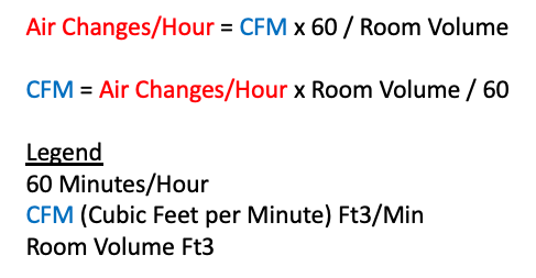
The formula for Air Changes per Hour looks like this:
How to calculate air changes per hour. Formula for Air Changes per Hour
Air Changes per Hour = CFM x 60 / the Volume of the room
We can express it another way in order to calculate CFM as
CFM = Air Changes / Hour x Volume of room / (60 Minutes/Hour)
High Rates of ACH for Cleanrooms
Cleanrooms are hidden from our view but they are used throughout the industry for businesses such as Food Manufacturing, Pharmaceuticals, electronics manufacturing of computer chips, and any product requiring a clean environment.
Cleanroom Air Changes per Hour
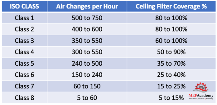
Cleanrooms require large amounts of air to be recirculated through the filters to achieve a certain level of cleanliness. Cleanrooms are classified according to ISO levels 1 through 8, with ISO Class 1 being the most stringent or cleanest.
ISO Classification of Cleanrooms – Air Changes per Hour
An ISO Level 1 cleanroom can require in the range of 500 to 750 ACH and require approximately 80% to 100% of the ceiling to be covered in filtration. ISO Class 8 can require in the range of 5 to 60 ACH and have a ceiling coverage rate of 5 to 15%.
For a cleanroom air change rate example let’s use the following information given to use by the owner.
Space is to be a Class 1 Cleanroom
The measurements of the room equal 12 ft x 20 ft x 9 ft
And the Requirements are 500 Air Changes per Hour minimum
Step 1 is to Determine the Volume of the Room
12 ft x 20 ft x 9 ft = 2,160 ft3
This is the volume that needs to be removed from the space every hour multiplied by the number of air changes required in an hour. The thing to remember is that this is in ft3 an hour, and we need to get the units to minutes, as in cubic feet per minute (CFM).
Step 2 – Determine Required Recirculation CFM
CFM = Air Changes / Hour x Volume / (60 Minutes/Hour)
CFM = 500 ACH x our volume of 2,160 ft3/ divided by 60 to get us to minutes, not hours.
CFM = 18,000
For our second example we’ll use a Hospital
Air Changes for Hospitals
The ACH rate is a common design requirement for various rooms within a hospital. Critical spaces within hospitals require that a certain amount of ventilation air be brought into the room every hour in addition to that, there is another requirement to recirculate the full volume of air a minimum number of times through the system every hour.
Hospital Air Changes per Hour
For example, a Recovery Room may require 2 ACH of ventilation air with a minimum air change rate of 6 for the space. This will require that the volume of outside air for ventilation be two times the volume of the space within an hour and another 4 ACH recirculated through the HVAC system for a total of 6 ACH.
The difference between a hospital room like an operating room and a cleanroom, is that the operating room doesn’t allow the air to be recirculated within the space, as opposed to a cleanroom where the use of fan powered recirculation units are acceptable to achieve the required cleanliness level.
Increased air exchanges reduce odors, increase air quality and cleanliness. There is obviously a cost to increasing the quantity of air changes due to the consumption of fan and or compressor power. Providing the correct amount of air and no more is critical to providing an energy efficient system. When critical spaces are unoccupied, the air change rate should be setback to lower volumes or turned off if allowed.
We used the same volume as the previous example so that you can see what the difference is between the two air change rates.
Hospital Recovery Room ACH
The space Volume is the same as before at 12 ft x 20 ft x 9 ft
The Requirements are 2 ACH of Ventilation with a 6 ACH Minimum
Step 1 again is to Determine the Volume of the Room, which is 2,160 ft3
Step 2 – Determine the Required Ventilation CFM
CFM = 2 ACH x 2,160 ft3/60
CFM = 72
Step 3 is to Determine the Required Minimum CFM
CFM = 6 ACH x 2,160 ft3/60
CFM = 216
Step 4 is to Determine the Required CFM to be Recirculated through HVAC Equipment
Minimum ACH – Ventilation ACH = Recirculated ACH (This can be stated in CFM)
How occupancy and Vacancy Sensors Work. Where should occupancy sensors be used, and which type is better, hard wired or wireless? What’s the difference between an Occupancy Sensor and a Vacancy Sensor? What does ASHRAE 90.1 require for the controllability of lights in various spaces? Lighting consumes up to 20% of the total energy in commercial buildings. By adding lighting controls considerable energy can be saved based on space usage type and the type of light source, such as incandescent, fluorescent, high intensity discharge or LED.
Occupancy sensors are used to detect motion and provide a response by turning on or off lights or HVAC equipment. By monitoring when spaces are being used, a more energy friendly support system of lights and HVAC equipment can be deployed. Various sensing technologies are used, such as Passive Infrared (PIR) and Ultrasonic. There are other technologies such as Time of Flight (ToF), microwave, and camera based technologies that are not covered here.
Hard Wired and Wireless Passive Infrared Occupancy Sensor
Energy Savings Potential
According to a Commercial Building Energy Consumption Survey, the following savings can be achieved using occupancy sensors for the various space usage types.
Energy is saved by reducing lighting levels or shutting them off when a space is not in use. By adding lighting controls, you can save up to 90% or more of the energy used depending on the space usage type.
Types of Occupancy Sensors
Communication from the sensor can be hard wired or wireless. Although most sensors are probably hard wired there are some advantages to using wireless sensors in certain applications. Wireless sensors can be battery operated or use photovoltaic (PV) powered sensors and can be easily attached to a wall or ceiling. They’re a possible option where it’s difficult or aesthetically unappealing to run electrical wiring.
The material cost for wireless occupancy sensors is usually more than hard wired, but there will be labor savings from not having to install electrical wiring. Also, the ability to easily move a wireless sensor makes more sense for spaces with frequent layout changes.
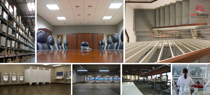
Where Should I Use an Occupancy Sensor?
The best candidates for occupancy sensors are spaces that are used intermittently, like bathrooms, meeting rooms, storage areas, classrooms, warehouses, private offices, and breakrooms. Areas to avoid putting sensors in are those that are busy or have a consistent occupancy level during a fixed schedule.
Locations for Occupancy Sensors
Two Lighting Control Strategies
The lighting can either automatically turn on when someone enters the room or require the occupant to manually flip a switch. These are referred to as an Occupancy or Vacancy sensor. The difference is that the vacancy sensor needs to be manually turned on, while the occupancy sensor turns on with motion. When the occupant leaves the room, both strategies will have the lights automatically shut off after a certain amount of time.
How do Occupancy Sensors Work?
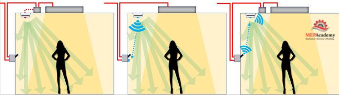
The problem for the occupancy sensor is to accurately detect when occupants are present and when they have left the space. This includes the ability to recognize occupants working at their desk or on the other side of a partition. There are various occupancy sensors that accomplish these problems better than others. Here are some of the sensor technologies being used and their advantages and disadvantages. The two most used occupancy sensors are either ultrasonic sensors or passive infrared sensors.
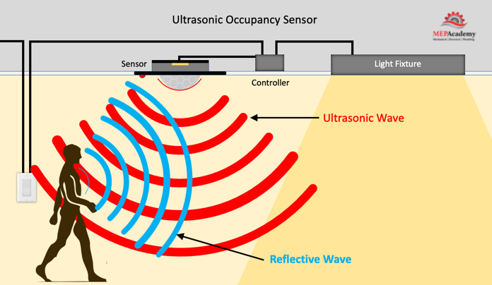
Ultrasonic Sensors
An ultrasonic sensor will emit high-frequency sound waves that bounce around the room and objects, but are not heard by humans. The sensor will pick up any movement by noticing a change in sound wave frequency. This is based on the Doppler effect or Doppler Shift, which is the change in frequency of a wave in relation to an observer who is moving relative to the wave source.
Ultrasonic Occupancy Sensor
Since the Ultrasonic occupancy sensor sends out a continuous signal, the electrical power consumed will be higher than the wireless passive infrared sensor. This will require the ultrasonic to most likely be hard wired to provide the constant energy for operation.
Ultrasonic sensors are good at detecting movement that may occur behind a partition or bookcase which isn’t in the direct line of sight of the sensor. This technology will pickup slight movements of an occupant sitting at their desk reading a book or typing on their computer.
The ultrasonic occupancy sensor has a greater detection range than the Passive Infrared Sensors.
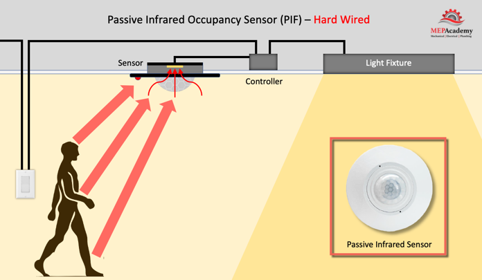
Passive Infrared Sensors (PIR)
An infrared technology-based occupancy sensor is best used in smaller open spaces without obstructions that allows it to easily detect movement. These sensors require that the movement occur within their direct line of sight, as they won’t detect movement behind a partition or bookcase.
Passive Infrared Occupancy Sensor
It’s called passive infrared because it doesn’t send a signal out. The sensor contains a thin film that generates electricity when exposed to heat which occurs when infrared energy is emitted from a warm object passes in front of the floor or wall in line of sight of the sensor. Because the infrared sensor doesn’t constantly send out a signal like the ultrasonic sensor, it doesn’t require the same amount of electrical power. This makes the passive infrared sensor a great option for wireless communication using a battery or PV cells for power.
The wireless passive infrared sensor will need a source of power for the controller that receives the signal from the sensor and interprets an output signal to increase or decrease lighting levels.
Wallbox sensors are made to fit in a standard electrical switch wallbox and use the voltage available at the box. This makes for an inexpensive and easy retrofit of an existing wall switch. They are limited by their range of vision.
How Long Should Lights Remain on After No Motion is Detected?
The time between no motion being detected and the shutting off or minimizing of the lights is dictated by various standards and codes. The National Electrical Manufactures Association (NEMA) has recommended that 15 minutes after no motion has been detected the interior lights should be shut off, and the 2021 IECC and ASHRAE 90.1-2019 have it at 20 minutes. Exterior lighting and parking garages have different requirements The shorter the time delay the greater the energy savings, but you also want to be sure not to have the lights going on and off too frequently.
Restrike Time
Occupancy sensors work best with light sources that have quick restrike times, that’s the amount of time it takes the light source to reach full value. Anyone who has witnessed the outage of a High Intensity Discharge light knows that it takes up to 15 minutes to reach full value. An outage occurred during a recent night-time football game, which had to be postponed long enough for the HID lights to come up to full brightness. This means that occupancy sensors are not a good choice for HID type lights but work well with quick starting light sources like LED, Incandescent and Fluorescent.
Where Should Sensors be Installed?
Sensors are best installed on ceilings or walls where interference from doors or air conditioning air flows are not a problem. Wireless sensors can be installed anywhere if motion is within the line of sight of the sensor. This allows wireless sensors to be installed where hard-wired sensors would be difficult to install.
Range of Sensors (Field of View and Coverage)
Wireless sensors need to be within 15 feet of the floor area or door to work effectively. Check the occupancy sensors manufactures literatures for specifics. If there are multiple obstructions in the space like partitions or bookcases, it may make sense to install hard-wired Ultrasonic type sensors which are better at motion detection in these situations. If wireless sensors are preferred, then more sensors will need to be installed to ensure motion is detected behind any obstructions.
Coverage or field of view can be in a narrow band like 8-degrees for use in corridors or aisles, up to a 360-degree circle, or a 180-degree semi-circle with diminishing capabilities at the extreme angles, and greater distance sensing abilities straight ahead. Sensors are also indicated by their coverage in square feet.
Multiple Levels of Lighting
In areas where there is natural sunlight, there is the option of using bi-level switching. The sensor will detect various levels of natural light and reduce the light fixtures output by half or some other percentage. Existing LED and fluorescent lights may need their ballast or drivers replaced to be compatible with the bi-level capabilities.
HVAC Controls and Occupancy Sensors
Occupancy sensors can save energy when integrated into the HVAC system control sequences. If the room is unoccupied, a signal can be sent to the HVAC equipment to reset the temperature, reduce the airflow or shut the system off. This would reduce energy consumed to condition an empty space.
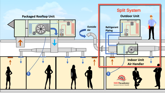
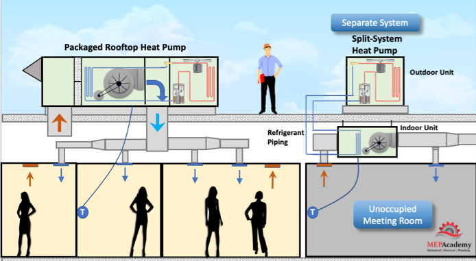
How HVAC Split System Air Conditioners Work. Using a Split System Air Conditioner or Heat Pump is common in residential and commercial applications. It’s called a split system because the indoor and outdoor components are separated or split from each other and are connected by refrigerant piping and control wiring. This differs from a self-contained rooftop packaged unit which houses both indoor and outdoor components. We’ll see different designs using split systems.
HVAC Split systems are convenient to use with existing buildings because it’s much easier to route small refrigerant piping to the indoor coil, then to run much larger air ducts using a rooftop packaged unit. As you can see the rooftop unit needs large openings for the supply and return ducts to enter the building. The split system uses smaller copper tubing and requires a small opening in the roof or wall.
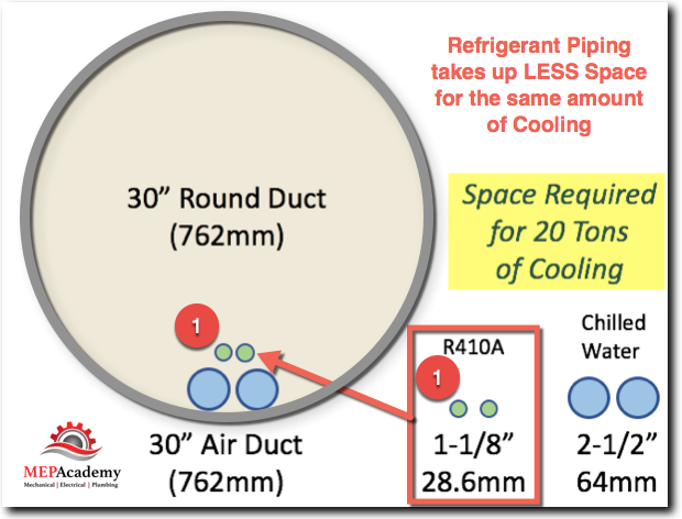
Refrigerant Piping Size vs Ductwork Size
Refrigerant carries more heat capacity then air, which allows small refrigerant piping to easily maneuver through building structures and components as opposed to large air ducts. This is what gives split systems their advantage, except when it comes to ASHRAE 62.1, ventilation air requirements, which we’ll discuss later.
Refrigerant Piping Space required versus equivalent Ductwork Space required with equivalent tonnage capacity
The split system is made up of the Outdoor unit, often called the condensing unit, because this is where the refrigerant condenses from a gas back into a liquid, and an indoor unit where the evaporator is located. The indoor unit can be called an Air Handling Unit (AHU), Fan Coil or a Furnace with Coil.
Split systems are available from less than one ton to over 100 tons of refrigeration capacity. Split systems come in two basic configurations, either as cooling only or as a Heat Pump, which we’ll explain later.
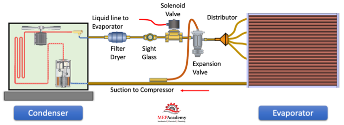
Refrigerant Cycle Split System HVAC
Heating in HVAC Split Systems
Heating can be in the form of a gas furnace, electric strip heater, electric heat pump, hot water, or steam. Here we show two ways of getting heat to the occupied space using a split system. First you can use a split system heat pump, which works to cool the space in summer, and heat the space in winter. See our video on How Heat Pumps Work to understand how they work.
Furnace with DX Coil
The other option is to install a furnace with a coil. The furnace will require some form of fuel such as natural gas for heating. Cooling will be accomplished by installing a evaporator coil on top of the furnace, which is connected to an outside condenser.
HVAC Split System with Furnace and DX Coil
The furnace will require combustion air inlet and a means of exhaust combustion gases outdoors. It’s important that the discharge flue remain a minimum of 10 feet away from any air intake, check your local code for the proper distance.
You’ll need to install a condensate drain pipe from the cooling coil drain pan to an approved receptor, like a floor sink or the tailpipe of a sink.
Electrical will need to be installed from a breaker panel to a disconnect switch located near the equipment. The disconnect switch is a safety device that allows any technician working on the equipment to lockout the electrical power feeding the HVAC equipment.
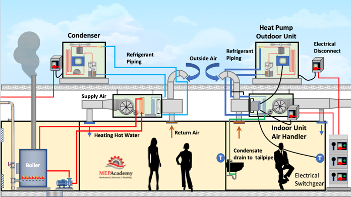
Heating Hot Water Coil
Another option is to use a boiler to provide heating hot water to a coil located inside the air handler. The boiler will need a source of fuel for combustion, in this case natural gas. The heating hot water will need to have a pump to circulate the water to all of the Air handlers in the building.
HVAC Split System using Heating Hot Water Coil for Heating
Here we only show one air handler getting heating hot water, but it could also be dozens more in larger buildings. The heating hot water piping will need to be insulated, most likely with some form of fiberglass pipe insulation to prevent the loss of heat from the pipes. Not shown is makeup water and any other accessories like expansion tanks. This could also be a steam boiler with a steam coil in the air handler to provide heating.
Ventilation Air per ASHRAE 62.1
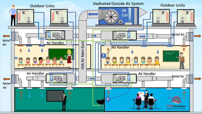
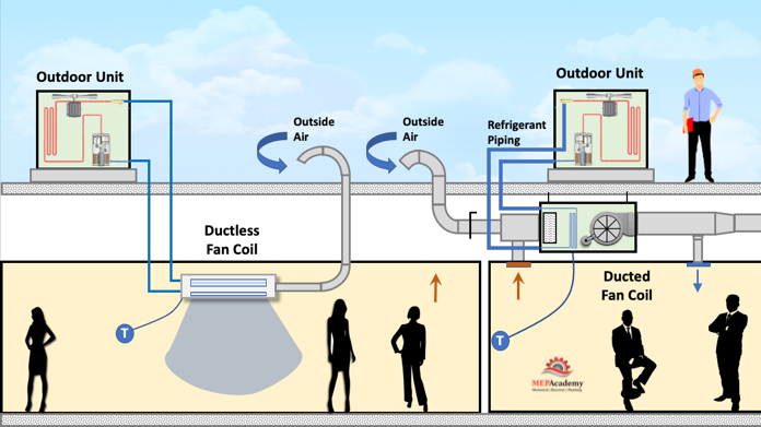
One of the challenges for split systems is providing the required ventilation air to each of the air handlers. Ventilation air will need to be provided to each space or indoor fan coil or air handler per ASHRAE 62.1. This requires a duct from the outside or from a DOAS unit to the space or fan coil. See our video on “Dedicated Outside Air Systems” for a better understanding.
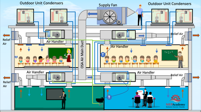
HVAC Split System with DOAS Unit for Ventilation Air
Dedicated Outside Air System
This Dedicated Outside Air System filters and conditions the outside air before the fan sends it to each of the air handlers. The Dedicated Outside Air System handles the latent load of the ventilation air so that the air handlers won’t need to be upsized for this additional load.
Each air handler will receive the required amount of ventilation air per ASHRAE 62.1 based on the occupancy level, size of the room and space usage type.
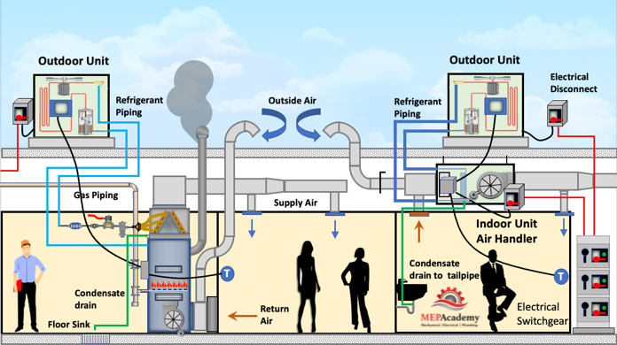
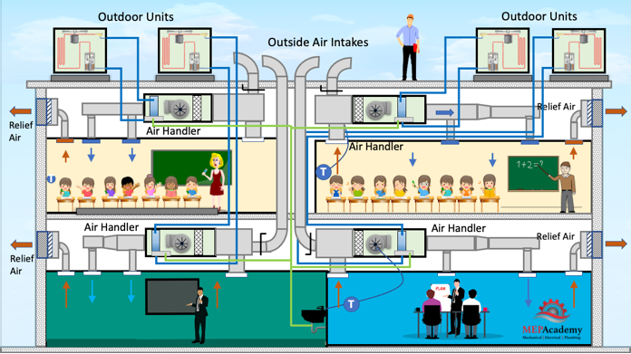
Supply Fan with Filtration
Another option is to provide ventilation air using just filtration and a supply fan, but no conditioning of the outside air. This relieves the indoor air handlers fan from needing to pull in outside air. The disadvantage is that the air handler will need to handle the additional heating and cooling load for the ventilation air.
HVAC Split System Air Conditioner using Filtered Ventilation Air
Separately Ducted Outside Air Ducts
The lowest first cost option would be to duct the ventilation air individually from each indoor air handler. This would require additional energy of the air handler fan and coil. This would require a lot of small ducts running through the building from each air handler, unless you required an economizer for your indoor air handler because it meets the threshold of your energy code, then the ducts would be much larger and may not make sense.
Split System HVAC Unit with Individually Ducted Outside Air
As shown before, each air handler has a condensate drain going to the tailpiece of the sink.
Condensing Unit
The condensing unit contains two major components, the compressor, and the condenser coil. The compressor is the heart of the unit and pumps the refrigerant around the piping circuit. The condenser coil provides a means of rejecting the heat to the outdoors using a fan blowing air over a hot coil.
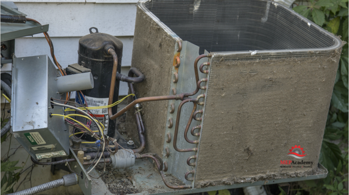
In this picture we can see that this condenser hasn’t been maintained and is covered with dirt. This will reduce the capacity of the unit, so be sure to check your outdoor coil at least once or twice a year to ensure its clean.
Condenser Unit with a Dirty Condenser Coil.
We can see the hot gas discharge piping coming off the top of the compressor and feeding the condenser coil which is responsible for rejecting the heat from the building. But in this poor condition it won’t be working. Here is the filter drier that’s on the hot liquid line leaving the condenser and sending liquid to the expansion valve at the evaporator. Here is the suction piping that has arrived from the indoor evaporator section and is entering the compressor below the discharge piping.
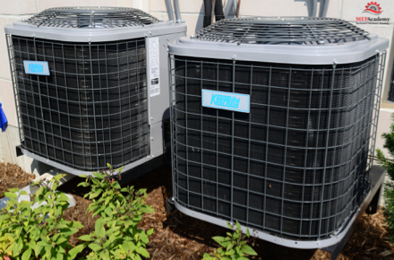
This is the ugly insides. Here is what the condenser may look like from the outside.
HVAC Condenser (Outdoor Unit)
There will also be some controls on the outdoor unit that communicates with the indoor unit and provides various safety components to protect the compressor and the other system parts. The communication from a thermostat or space sensor is typical for a residential unit, while in commercial installation there could be the addition of a BACnet card that allows communicating with a Building Automation System (BMS).
Outdoor units will contain one compressor for smaller sizes and multiple compressors for larger systems.
The condenser can also be air-cooled, water-cooled or evaporatively cooled.
Indoor Unit Air Handler (DX Fan Coil)
The Air Handler contains the indoor fan and evaporator coil. The evaporator coil is where the refrigerant absorbs the heat from the building air that is being blown over the coil. This causes the refrigerant liquid in the evaporator to evaporate while cooling down the building air, see our video on “Refrigerant Cycle 101” to better understand how a refrigeration cycle works. The expansion valve or metering device separates the high side from the low side and modulates the amount of refrigerant that passes through it in relationship to demand.
The indoor unit can be ducted or ductless.
Ductless and Ducted Air Handlers or Fan Coil in a Split System HVAC Unit
Residential systems are relatively simple and smaller, while the commercial versions can be very large and have many other options installed within their housing. Commercial air handlers can be packaged, custom made, or built-up with individual components selected and field erected. See our other video on “Air Handling Units” for a better understanding.
Compressors
The smaller residential units under 10 tons will most likely have 1 compressor, while commercial units 10 tons and over can have two or more compressors. Compressors vary in their ability modulate capacity. Smaller system will use a hermetically sealed compressor with a scroll compressor. Larger systems can use semi-hermetic, reciprocating, and scroll compressors in 1 or more configurations depending on size.
Most compressors use oil for lubrication and that oil travels around the refrigerant circuit continuously during operation. It’s important that the oil returns to the compressor at the same rate that it leaves, as the compressor needs to remain lubricated at all times.
Heat Pumps
In addition to the cooling only split systems, there are Heat Pumps which reverse the refrigerant cycle to provide heating also. There is a move in some states and countries to go all electric, such as in California. Heat Pump are all electric so there is no burning of a carbon-based fuel. See our other video on “How Heat Pumps Work” for a better understanding.
One of the differences between a Heat Pump and other cooling only units is that of the metering device. The metering device separates the high-side from the low-side and controls the amount of refrigerant passing through it. The Heat Pump uses a special “Reversing Valve or 4-Way Valve” that allows refrigerant to change direction based on whether in heating or cooling mode. The indoor coil is used as an evaporator to provide cooling during summer, and as a condenser to provide heating during winter. Therefore, you shouldn’t call the outdoor unit a condenser when dealing with a Heat Pump, as it acts as both a Condenser and Evaporator depending on the mode of operation (Heating or Cooling). With a cooling only Air Conditioner, the outdoor unit is always the condenser.
Split System Sizing and Mixing and Matching
Splits systems are often chosen where the outdoor and indoor unit tonnage match, but that is not always the case. Split systems can have the outdoor unit slightly larger or smaller than the indoor unit. By upsizing the outdoor unit, this will allow more latent heat for the indoor unit. The tonnage of the indoor unit can be larger than the outdoor unit to increase the sensible heat ratio and airflow (CFM). Providing an indoor unit that is one size larger or smaller than the condenser maybe safe, but check with the AC Manufacture when mixing outdoor units and indoor unit capacities. This is not allowed with most Heat Pumps.
Residential systems commonly use split systems of 5-Tons and under or multiples of these sizes for larger homes. You might find a 3-Ton unit serving the first floor and another 3-ton unit serving the 2nd floor in a two-story home.
Refrigerant Piping and Number of Circuits
For small split systems where the indoor and outdoor units are relatively close and the pipe routing simple, the use of line sets maybe used. Line sets are available in a coil of ACR copper and are pre-charged with refrigerant, in lengths of 15, 25, 35, 50 or 100 feet. This saves on labor by avoiding field brazing of joints for fittings and couplings. Piping distances are often restricted by equipment manufactures so be sure to check the literature for these requirements if your distances exceed 100 feet or more.
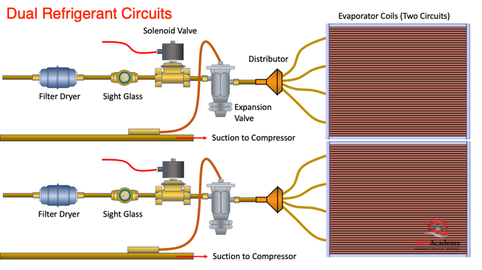
Dual Refrigerant Circuits in a Split System Air Conditioner
Most small split system have only one circuit, but as the HAVC unit gets larger there are dual circuit units available. Dual circuits will require twice as much piping as a single circuit HVAC unit. There will be two suction lines and two liquid lines running from the indoor unit to the outdoor unit. With dual circuits the ability to control capacity is increased in addition to having a backup or redundant circuit incase a compressor burns out. Each circuit has its own compressor.
The DX coil can also be setup in either a single or dual circuit arrangement. The refrigerant can pass through the coil using one path or two. If you’re using a dual circuit condenser than you’ll have a dual circuit indoor coil. Its possible to have a single circuit condenser and a dual circuit DX coil.
Refrigerant Piping Insulation
This is where most installations that we review are lacking in code compliance and application. The proper application of insulation is important in maintaining a well-functioning HVAC split system. If insulation is poorly applied or if the wrong insulation is used, then there will be a LOSS in capacity of the system. This means that the number of tons of air conditioning that was installed will be less than that. See our video on “Refrigerant Insulation” for the proper installation and type of insulation to be used when installing refrigerant piping.
Condensate Drain
Cooling coils remove moisture from the incoming air, and that moisture condenses on the evaporator coil. The water trickles down the coil and is captured in a drain pan that sits under the cooling coil. The drain pan needs to have some way to empty this accumulation of condensate water. Piping is provided from the drain pan to approved receptor, which could be a floor sink or the tailpiece of a regular sink.
The drain piping needs to pitch in order to avoid overflowing the drain pan. If the piping can’t be pitched per the slope required by the local code, then a condensate pump will need to be added. The condensate pump will raise the level of the water in the piping so that it can meet the required slope or pump directly to the receptor. See our Video on “Condensate Drain Piping”.
Controls
The controls on most split systems are very simple, especially residential split systems. A thermostat calls for heating or cooling and the system initiates startup. For systems with more than one circuit, if the first circuit can’t satisfy the demand then the second circuits solenoid valve would open adding additional cooling capacity to the system. The circuit board for controls is usually mounted in the outdoor unit with control wiring connect the indoor unit to the outdoor unit.
Adding Building Management System (BMS) oversight or connectivity is an option usually implemented on commercial properties. This allows the building engineer or management company complete oversight using graphical interfaces to see what is happening with each system connected to the BMS.
In addition to controlling the overall unit, the system has safety controls that operate to protect the equipment. This could include high and low pressure switches to prevent excessive and minimum pressure levels respectively. There are safety devices to protect the equipment from too much electricity or excessive temperatures.
Advantages and Disadvantages of an HVAC Split System Air Conditioner
One of the biggest benefits is that they come as a packaged unit, already engineered by the manufactured with matching outdoor and indoor units.
Split systems are less invasive for remodeling projects, allowing smaller refrigerant piping to be run to a space instead of larger air ducts. This is beneficial when the indoor space is several floors below the roof, as no vertical duct shafts are required as with a Rooftop unit.
Split system outdoor units weight less than a one piece packaged unit.
Split systems require smaller openings in the structure for refrigerant piping to pass from the outdoor unit to the indoor unit, as opposed to air ducts.
Split System outdoor units are smaller than Rooftop Units, so they are easier to hide. This can be important when the building has large skylights or line of sight code compliance issues.
Split systems usually cost more on new construction projects because they require several points of connection for the electrical and refrigerant piping to connect the outdoor and indoor sections together.
Split systems will require some method of getting the required ventilation air to each space or indoor fan coil per ASHRAE 61.2
Top 6 HVAC Control Strategies to Save Energy. In this video we’ll learn the top 6 Control Strategies for reducing energy consumption. These are control strategies to reduce cost and save energy. The control strategies are programmed into the sequence of operation for the control of HVAC systems.
We’ll learn about using trim and respond (T&R) setpoint reset logic for controlling chillers and air handlers. The energy savings from these strategies vary by geographical area and building types.
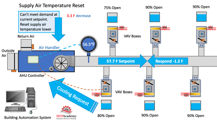
To save energy the supply air temperature can be reset higher when the demand is reduced. This will save on compressor energy use and allow more time for the use of the air side economizer.
Using Trim and Respond control logic if no request for cooling is sent to the air handler controller, than the supply air temperature is trimmed by a set value that is determined by the programmer. Let’s say that if no request is made the supply air temperature is reset 0.2°F, this would move our setpoint to 55.2°F. Every two minutes or whatever duration is set by the controls programmer the trimming of the supply sir temperature will occur until a request is made from a zone.
HVAC Controls Strategy – Supply Air Temperature Reset
The VAV zone boxes can be programmed to make a request when any VAV box damper reaches 90% open. When the request is sent, the supply air temperature will respond by decreasing by a certain value, chosen by the programmer, let’s say by 0.3°F. If our temperature was trimmed up to 58°F, before a request was made, the request would decrease our supply air temperature to 57.7°F.
If multiple VAV boxes send request at the same time, then the value is multiplied by the number of request. If 4 VAV Boxes sent a request for more cooling, then the Supply Air Temperature could be reset by 4 times 0.3°F, for a total of 1.2°F decrease. The controls programmer will limit how much the supply air temperature can be decreased at any one time, no matter how many request are sent for additional cooling. This allows system stability.
Systems using an air-side economizer will have more time when the economizer is in use because of the supply temperature being set higher. This allows the outdoor air to be used instead of the compressor to provide cooling, which saves on energy.
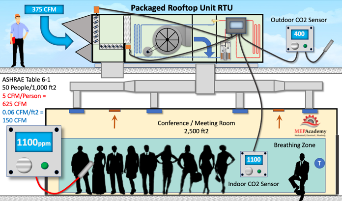
#5 Demand Control Ventilation
The reason it’s called Demand Controlled ventilation is that it controls the amount of ventilation based on the demand. Demand changes with occupancy levels, so some form of occupancy monitoring will be used as the control strategy. Ventilation air is required by ASHRAE standard 62.1, but providing ventilation air is energy intensive and costly. Providing only what’s needed can save on energy and money.
With ASHRAE 62.1 the ventilation requirements or outdoor air is increased based on the number of occupants and square footage of the space. Demand controlled ventilation is based on providing outdoor air in proportion to the occupancy level.
Energy is wasted in the form of conditioning excessive amounts of ventilation air when the occupancy level is less than the design maximum. By using demand-controlled ventilation, the occupancy level can be monitored, and the quantity of ventilation air adjusted downward according to actual occupant levels. Tracking the occupancy level with DCV reduces energy consumption by only bringing in enough ventilation air to satisfy the current level of occupants, not the design maximum.
Using a conference room for our example. If the meeting room was designed for 125 people, but only the presenter is currently in the room waiting for attendees. The CO2 monitor would pick up the low quantity of carbon dioxide and close the outside air damper to match the occupant level. As more attendees arrive to the meeting, the level of CO2 increases, and the CO2 Monitor picks up this increase and sends a command for the Outside Air Damper to open wider, allowing more outside air into the space. As, the occupants leave the system will begin to close the outside air damper. This is a basic explanation of how DCV works, for a further explanation see our video on Demand Controlled Ventilation.
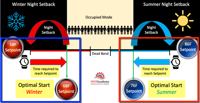
#4 Optimal Start
HVAC equipment has often been setup to use a time clock or time-of-day schedule to turn the system on and off based on a proposed occupancy schedule. The time clock will be set to start the HVAC system equipment before the occupants arrive and to shut it off at a preprogrammed time when the building is scheduled to be vacant. The schedule of when to turn on the HVAC equipment in the morning to ensure the space is comfortable for the occupants is often based on the worst summer or winter conditions. This creates an opportunity to save energy by providing an optimal start time when conditions are not at these peak conditions.
Optimal Start of HVAC Air Conditioning Equipment
With an Optimal Start strategy the building automation system will select the best, or optimal start time based on the conditions existing for that day. The buildings control system will determine how much time, or how early the HVAC equipment needs to be started to ensure the space is comfortable for the occupants when they arrive. The building automation system will prevent the HVAC equipment from starting too early, which is a waste of energy. The controls will ensure that the system is started with just enough time to have the space conditioned when occupants arrive, no sooner.
Using the capabilities of a building automation system to track historical data and use that data for current conditions is how this strategy is implemented. The controls system receives input from space sensors on the current temperature and compares this to the setpoint temperature. With historical trending data the building automation system can determine how long the HVAC equipment needs to run to make up the difference between this setpoint and the current space temperature. The greater the Delta-T, the earlier the HVAC equipment will be started.
This control strategy saves energy by optimally starting equipment and avoiding conditioning spaces to setpoint temperatures earlier than required. This saves on operational hours of the HVAC equipment, allowing the equipment to last longer.
#3 Shorten HVAC Schedule
Often HVAC schedules are set for longer time durations then the actual occupants require. Shortening the HVAC schedule works well with an optimal start and stop control strategy. This strategy avoids turning on HVAC equipment before they are needed and quickly turns them off when occupants are not scheduled to be in the building. The building automation system learns with historical trending data when it’s the best time to turn equipment on. The controls system uses outdoor air conditions, indoor temperatures and set points for heating and cooling during occupied mode.
There may be spaces within the building that operate only on specific days of the week. If this space is on the same system as the regularly scheduled equipment, it might payoff to provide a separate system or method of controlling the conditioning of this space.
HVAC Equipment operating Schedules – Separate System for irregular Scheduled Spaces
Working with optimal start to determine the best time to start the equipment, including night setback temperatures, this strategy ensures that the equipment is only running when the building is occupied.
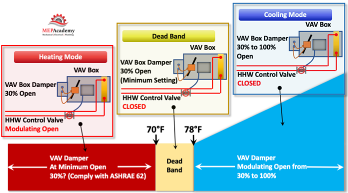
#2 Minimum VAV Box Damper Flow Reductions
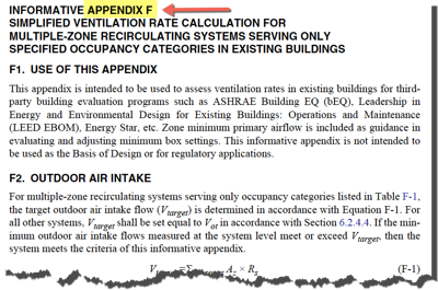
Systems using Variable Air Volume boxes have their dampers set to a minimum open position to ensure that there is always ventilation air per ASHRAE 62.1. Often this minimum open setting is greater than the actual CFM required of the space, as the space will most likely be influenced by the internal load which will drive the damper wider open, negating the minimum setpoint. Set the VAV box damper open to the minimum mandated to meet ASHRAE standard 62.1 for ventilation and no more. See ASHRAE 62.1 Appendix “F” for a Simplified Ventilation Rate Calculation for multiple zone recirculating systems.
ASHRAE Appendix F
When the minimum damper position is set too high, then fan and cooling energy is wasted. Too much cold air is being sent into the space, requiring additional energy to reheat the air. This can be avoided by reducing the minimum setpoint, and by using this Minimum VAV Box Damper Flow Reduction strategy. This will of course depend on the space type and usage.
#1 Wider Dead Bands and Night Setbacks
On average, this was the #1 way to save energy.
DeadBand
The deadband is the temperature range when the HVAC system is neither calling for heating or cooling.
HVAC Controls – Deadband (No heating or cooling called for)
By widening the dead band, the amount of time that the HVAC system would save energy would increase. In California zonal thermostats that are used to control both heating and cooling shall be capable of providing a deadband of at least 5°F.
Night Setback
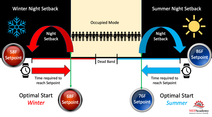
When the building is unoccupied during the nighttime hours, the HVAC system temperature can be setback in the range of 6° to 10°F. This allows the building to become warmer or cooler at night then during the day, but avoids letting it get too far from setpoint. By allowing the HVAC system to increase or decrease from the setpoint, depending on whether in cooling or heating mode, the system will come on less during the night when the building is unoccupied, thereby saving energy.
HVAC Controls – Night Setback and Optimal Start Control Strategies
The system will come on only to avoid extreme temperature conditions. For instance, if your normal daytime setpoint for cooling is 76°F, you could program the DDC system to bring on the HVAC equipment to cool the space after hours or off schedule if the building temperature reached 86°F.
You can see that this works directly with the Optimal Start Control Strategy which is to ensure there is enough time in the morning to cool the space down to its normal setpoint. This is because it was prevented from maintaining normal setpoint temperature of 76°F during the night, hence night setback.
It’s important the system be put in the unoccupied mode; this is to ensure that the outside air dampers are closed. Bringing in ventilation air in unoccupied mode can increase energy consumption unless outdoor conditions are in the economizer range for free cooling of the space in summer.