Chapter #7 – General Conditions (MEP Estimating Spreadsheet)
We consider other cost to include general and special condition items, and indirect expenses, those items which are indirectly related to the construction of the project, but which are still required. We will cover the most common of these and how to figure them.
We like to have a separate form with many of the general and special conditions normally found on HVAC projects shown with their cost per unit already on the estimating sheet for quick reference. This will help you remember the most common items and the value that you use for them in each estimate.
General Conditions – Management
Below is the top portion of the General Conditions tab of the MEP Academy estimating spreadsheet. Your company may use something different but the ideas and concepts of these cost are similar. It doesn’t matter where you locate these cost in your spreadsheet, so long as you have covered their cost if required.
We will cover the most commonly used general conditions for a new construction project.
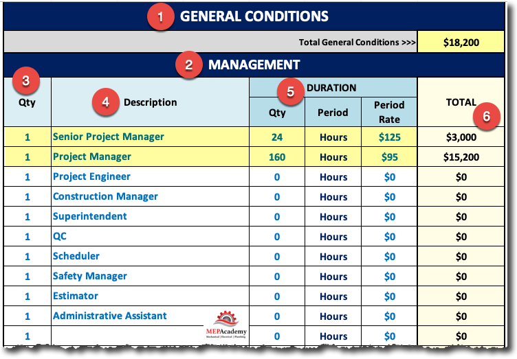
Project Managers
The project manager will oversee all aspects of the project including the project schedule and depending on the company; the project manager could be responsible for estimating, purchasing equipment and materials, and total oversight of the construction.
Project managers can manage many small projects or one large project. The cost of a project manager can be charged to each job for the time spent on that project. You can determine how much project management time you believe the project your bidding will need. Knowing what a project managers cost is allows you to prorate the expense for the duration of the project. You could also charge for the project manager as a percentage of the total cost of the project, such as 5%.
Project Engineers
Project engineers provide useful assistance to the project manager by doing some of the more mundane task of running a project, like preparing submittals, O&M manuals, chasing down drawing revisions and assisting in the overall running of the project. Project engineers are usually overseen by an experienced senior project manager and are more common on larger projects that require additional support for efficient execution of the project requirements.
Superintendent
The superintendent provides oversight of the labor force and coordinates with the project manager and subcontractors on labor aspects. A in company signatory to a union this would be the role of a union worker. For smaller companies this role might be carried out by the project manager.
Safety Managers
Depending on the size of the project and the requirements you could be required to provide a safety manager. The safety manager would be responsible for making sure that the workers follow the project safety requirements, such as wearing hardhats and googles, the proper use of equipment and tools, along with conducting safety tailgate meetings. The safety manager will be responsible for providing training of the field personnel, filing reports and recording any violations of the safety requirements.
Project Estimators
Depending on how your company is setup, the responsibility for pricing change-orders could be allocated to the project manager and his/her team or sent to the estimator located in the offsite company offices. Projects with a lot of change-orders should have the assistance of the estimating department so as not to stifle the project team. The estimating department is better setup to handle change-orders using their estimating software program.
Project/Administrative Assistants
Depending on the size of the project, additional jobsite office personnel maybe required to process all the correspondences and demands of a construction site that isn’t already covered by the project manager or project engineer.
Construction Office – Non-Reoccurring Cost
Non-reoccurring cost are those that will impact the project as a one-time cost as opposed to a monthly expense
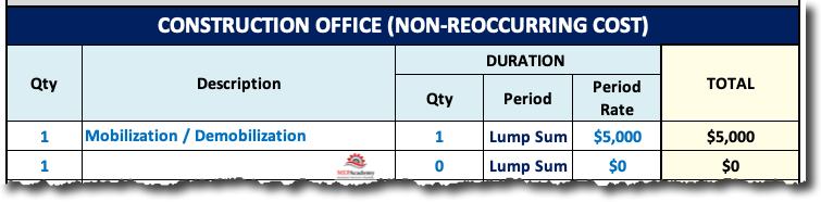
Job Office Mobilization and Demobilization
This is the cost to have the office trailer brought in and setup, then torn down at the end of the project. This cost is independent of the monthly rental fee for the office trailer. Mobilization and demobilization also includes the cost of moving tools and equipment to the site for the execution of the scope of work, and then for the pickup of that equipment and tools at the end of the project.
Construction Office – Reoccurring Cost
Reoccurring cost are those that will impact the project on a monthly or regular basis, as opposed to a one time expense.
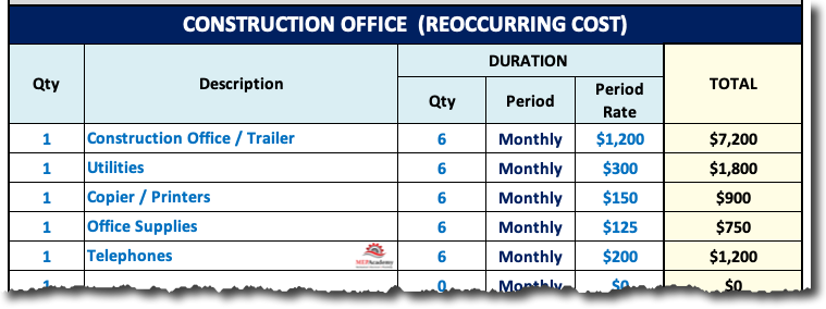
Job Office Rentals
Jobsite trailers or offices will be required on larger new construction projects as there is nowhere on site for you to conduct the administrative functions of the project. You will need an area to review drawings, and office space for your jobsite personnel.
Job Office Utilities
This is the cost incurred for the use of electrical power, water and gas. Often the general contractor will provide this at no charge, but it’s important to confirm who is paying for these cost.
Job Site Office Telephone/FAX
It’s possible that the project will require a landline and not just the cell phone of the jobsite personnel. You need to figure how long the project is going to last and the monthly cost for the service and usage fees if required.
Job Site Office Supplies
This might include paper for the copier, FAX machine or plotter, along with coffee, cups, sugar, creamer, water and miscellaneous supplies. Plug some value for the duration of the project based on your companies past experience for these type of office consumables.
Parking
Is there adequate onsite parking, or will you be required to rent offsite parking,? Will you be responsible for paying for onsite parking fees? Some of the Universities require the contractors to buy parking permits for the duration of any parking required by their vehicles.
It’s important to know if parking fees will be required to be paid by your company for any vehicles parked at the project site during the renovation or new construction. Area’s around large metropolitan cities, and at some of the Universities during school sessions are crowded and parking is limited. In certain cases you may be required to pay for your own parking.
Additionally, you may be required to bus workers in to the site if parking is provided remotely. Depending on your labor agreement, you may be responsible for getting field labor back to their cars by the end of the day, instead of at the gate or on the site of the project. This would require that you figure losing part of the work day to transporting your field labor.
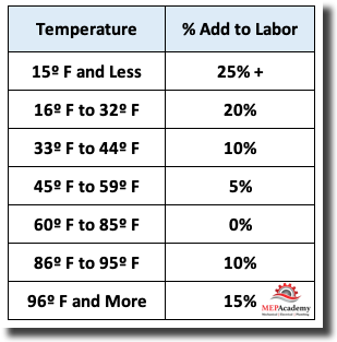
Temporary Heating or Cooling
This requirement can often be found in the general requirements of the specifications. Add the cost to provide portable heaters or coolers as required. If the temporary system is large, then you will need to contact one of the equipment rental companies that specialize in providing and hooking up temporary systems.
Storage
You need to determine if there is an area on the project site that is allocated for your company to store materials as they are being staged for installation. Unless the project is being run under some form of Lean Construction where just in-time deliveries are being made on the day the material will be used then some location on site will be required to store and stage material from. If there isn’t any space within the building to store building materials, then you’ll need to rent a lockable storage bin in order to store tools and materials.
Subsistence and Travel
Jobs that require your workers to work beyond certain boundaries as established by the unions, or for which the project is located out of town, and for those you will be sending will require subsistence.
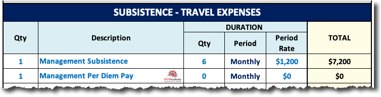
Subsistence helps to compensate the employee for additional expenses incurred while away from home performing his/her duty as an employee. Depending on the location this could include a cost of living increase, as some cities and areas are more expensive than others. The employee may need to stay in a hotel or rent a temporary apartment for the duration of the project as it the distance would make it impossible to drive to the site and back daily. The renting of a vehicle may be required along with round trip airfare.
If you work for a union company then check the union agreement as to the daily subsistence rate for any employee that is required to travel beyond the allotted free zone. If the union employee uses their own vehicle make sure to check the union agreement for any required reimbursement of mileage driven to and from the project site. Most times the union employee is required to get to the project site at their own cost, unless it exceeds a certain distance from the designated union zone map epic center.
Other Cost
As-built Drawings
The requirement to provide as-built drawings or record drawings of the actual installation, should be stated in the specifications. This is almost certain to be a requirement on most projects, and even if it wasn’t a requirement, it is good business practice to provide the owner with a record of the actual installation. This could be as simple as marking with a red pencil or pen the actual routing of ducts and pipes including any size changes.
Liquidated Damages
You won’t put any cost for this in your estimate as the intent is to complete the project as defined in the specifications to avoid incurring a liquidated damages penalty. This might be found in the section entitled progress schedule, where it states that if the project goes past its scheduled completion date, there will be damages assessed. This is a penalty for delaying the completion of the project, and is usually stated in so many dollars per day for every day that you pass the scheduled completion date.
Get a copy of the MEP Academy Estimating Spreadsheet here >> MEP Academy Estimating Spreadsheet

Understanding the MEP Estimating Spreadsheet (Free Course)
- Chapter #1 – HVAC Equipment
- Chapter #2 – HVAC Quotations
- Chapter #3 – Subcontractors
- Chapter #4 – Sheet Metal Material and Labor Summary
- Chapter #5 – Labor Rates
- Chapter #6 – Rentals
- Chapter #7 – General Conditions
- Chapter #8 – Finalizing the Estimating Spreadsheet